


ASUS CUC2 User’s Manual 35
3. HARDWARE SETUP
Connectors
3. H/W SETUP
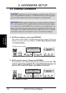
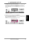
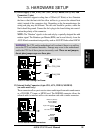
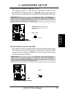
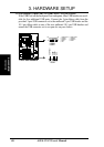
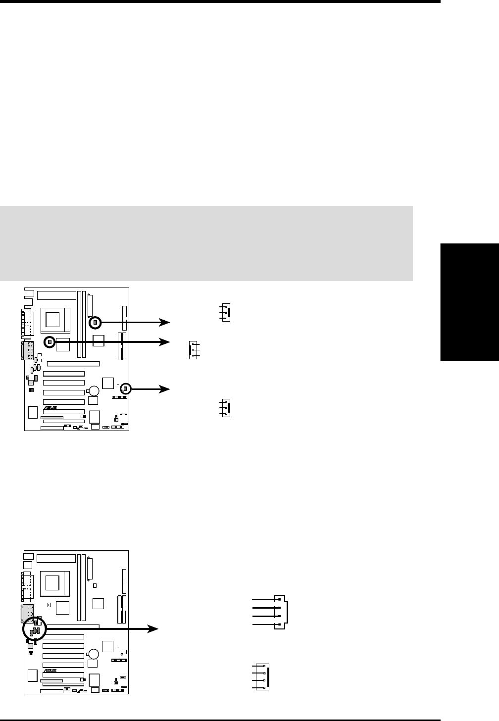
11) Power Supply (PWR_FAN), CPU (CPU_FAN), Chassis (CHA_FAN) Fan
Connectors (3 pins)
These connectors support cooling fans of 350mA (4.2 Watts) or less. Orientate
the fans so that the heat sink fins allow airflow to go across the onboard heat
sink(s) instead of the expansion slots. Depending on the fan manufacturer, the
wiring and plug may be different. The red wire should be positive, while the
black should be ground. Connect the fan’s plug to the board taking into consid-
eration the polarity of the connector.
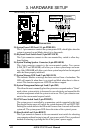
NOTE: The “Rotation” signal is to be used only by a specially designed fan with
rotation signal. The Rotations per Minute (RPM) can be read directly from the
ASUS iPanel or monitored using a utility such as ASUS PC Probe or Intel LDCM.
WARNING! The CPU and/or motherboard will overheat if there is no airflow
across the CPU and onboard heatsinks. Damage may occur to the motherboard
and/or the CPU fan if these pins are incorrectly used. These are not jumpers,
do not place jumper caps over these pins.
CUC2
®
CUC2 12-Volt Cooling Fan Power
PWR_FAN
CPU_FAN
GND
Rotation
+12V
CHA_FAN
GND
Rotation
+12V
GND
Rotation
+12V
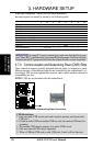
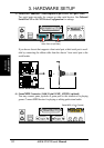
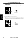
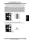
12) Internal Audio Connectors (4-pin CD1, AUX, VIDEO, MODEM)
(on audio model only)
These connectors allow you to receive stereo audio input from such sound sources
as a CD-ROM, TV tuner, or MPEG card. The MODEM connector allows the
onboard audio to interface with a voice modem card with a similar connector.
CUC2
®
CUC2 Internal Audio Connectors
Right Audio Channel
Left Audio Channel
Ground
Ground
CD In (Black)
AUX In (White)
VIDEO In (Green)
MODEM
Modem-Out
Ground
Modem-In
Ground