


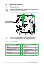
1-2 Chapter 1: Product introduction
1.2.2 Layout contents
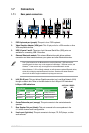
1.2 Motherboard overview
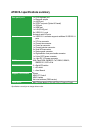
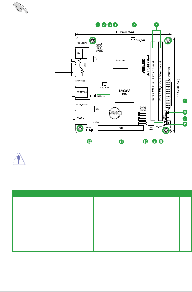
1.2.1 Motherboard layout
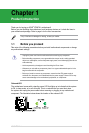
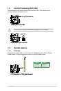
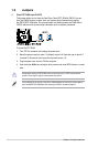
Place four screws into the holes indicated by circles to secure the motherboard to the
chassis. DO NOT overtighten the screws! Doing so can damage the motherboard.
Ensure that you install the motherboard into the chassis in the correct orientation. The edge
with external ports goes to the rear part of the chassis.
Place this side towards
the rear of the chassis.
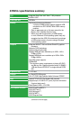
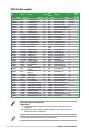
Connectors/Jumpers/Slots/LED Page Connectors/Jumpers/Slots/LED Page
1.
ATX power connectors (24-pin EATXPWR, 4-pin
ATX12V)
1-11 7.
Chassis intrusion connector (4-1 pin
CHASSIS)
1-13
2.
CPU, power, and chassis fan connectors (3-pin
CPU_FAN, 3-pin PWR_FAN, 3-pin CHA_FAN)
1-14 8. Onboard LED (SB_PWR) 1-1
3. USB connector (10-1 pin USB910) 1-13 9. Clear RTC RAM (3-pin CLRTC) 1-8
4. Atom 330 processor 1-3 10.
Serial ATA connectors (7-pin SATA1,
SATA2, SATA3)
1-12
5. DDR2 DIMM slots 1-3 11. PCI slot 1-7
6. System panel connector (10-1 pin F_PANEL) 1-15 12.
Front panel audio connector (10-1 pin
AAFP)
1-14