


ASUS AT3N7A-I 1-13
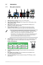
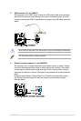
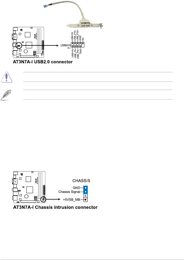
3. USB connector (10-1 pin USB910)
This connector is for a USB 2.0 port. Connect the USB module cable to this connector,
then install the module to a slot opening at the back of the system chassis. This USB
connector complys with USB 2.0 specication that supports up to 480 Mbps connection
speed.
Never connect a 1394 cable to the USB connector. Doing so will damage the motherboard!
The USB module cable is purchased separately.
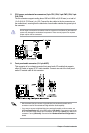
4. Chassis intrusion connector (4-1 pin CHASSIS)
This connector is for a chassis-mounted intrusion detection sensor or switch. Connect
one end of the chassis intrusion sensor or switch cable to this connector. The chassis
intrusion sensor or switch sends a high-level signal to this connector when a chassis
component is removed or replaced. The signal is then generated as a chassis intrusion
event.
By default, the pin labeled “Chassis Signal” and “Ground” are shorted with a jumper
cap. Remove the jumper caps only when you intend to use the chassis intrusion
detection feature.