


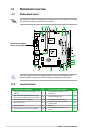
1-10 Chapter 1: Product introduction
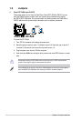
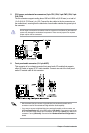
12. USB 2.0 ports 1 and 2. These two 4-pin Universal Serial Bus (USB) ports are for
USB 2.0 devices.
13. USB 2.0 ports 3 and 4.
These two 4-pin Universal Serial Bus (USB) ports are for
USB 2.0 devices.
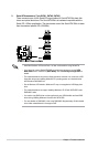
14. eSATA port.
This port connects to an external Serial ATA hard disk drive.
To use hot-plug, set the SATA Mode Select item in the BIOS to [AHCI Mode]. See section
2.3.4 Storage Conguration for details.
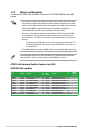
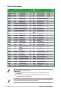
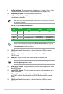
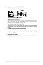
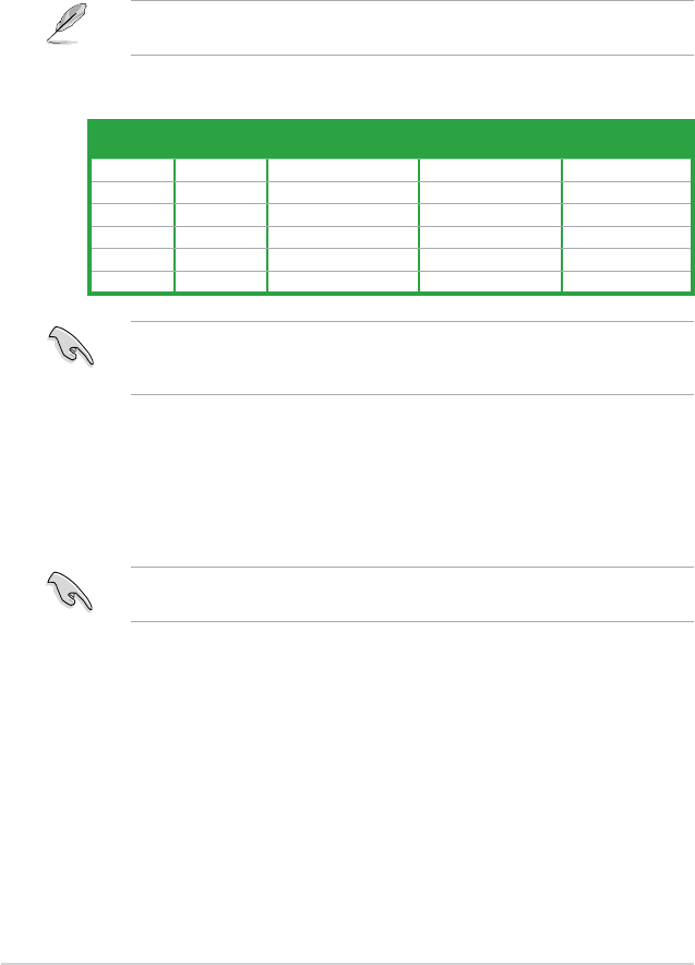
Audio 2, 4, 6, or 8-channel conguration
Ensure the audio device of sound playback is VIA High Denition Audio (the name may
be different based on the OS). Go to Start > Control Panel > Sounds and Audio Devices
> Sound Playback to congure the settings.
Port
Headset
2-channel
4-channel 6-channel 8-channel
Light Blue Line In Line In Line In Line In
Lime Line Out Front Speaker Out Front Speaker Out Front Speaker Out
Pink Mic In Mic In Mic In Mic In
Orange – – Center/Subwoofer Center/Subwoofer
Black – Rear Speaker Out Rear Speaker Out Rear Speaker Out
Gray – – – Side Speaker Out
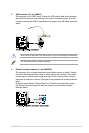
15. Optical S/PDIF Out port. This port connects to an external audio output device via an
optical S/PDIF cable.
16. Coaxial S/PDIF Out port.
This port connects to an external audio output device via a
coaxial S/PDIF cable.
17. HDMI port.
This port is for a High-Denition Multimedia Interface (HDMI) connector,
and is HDCP compliant allowing playback of HD DVD, Blu-Ray, and other protected
content.
18. USB 2.0 ports 7 and 8.
These two 4-pin Universal Serial Bus (USB) ports are for
USB 2.0 devices.
Refer to the audio conguration table below for the function of the audio ports in the 2, 4, 6,
or 8-channel conguration.
9. Line Out port (lime). This port connects to a headphone or a speaker. In the 4, 6 and
8-channel congurations, the function of this port becomes Front Speaker Out.
10. Microphone port (pink).
This port connects to a microphone.
11. Side Speaker Out port (gray).
This port connects to the side speakers in the
8-channel audio conguration.