


2-18 Chapter 2: Hardware information
2.4.3 Memory mirroring and sparing technology
The Intel
®
5400 chipset supports the memory mirroring and sparing technology.
Refer to the below sections:
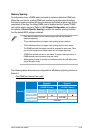
Memory Mirroring:
When enabling memory mirroring function in the BIOS setting (please refer the
section
4.4.2 Chipset Conguration
and congure the option
Memory Branch
Mode
as
Branch Mirroring
), Branch 1 contains a replicate copy of the data
in Branch 0. The DIMMs must cover the same slot position on both branches.
DIMMs that cover a slot position must be identical with respect to size, speed,
and organization. DIMMs within a slot position must match each other, but aren’t
required to match adjacent slot positions.
And the total memories size will be the half of all installed memories.
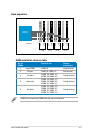
The below two memory congurations were required to operate in mirrored mode.
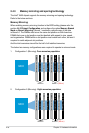
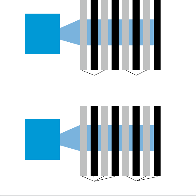
1. Conguration 1 (Mirroring):
Four memories population
DIMM 00 (Slot 0:Channel 0)
MCH
Branch 0
DIMM 01 (Slot 1:Channel 0)
DIMM 10 (Slot 0:Channel 1)
DIMM 11 (Slot 1:Channel 1)
DIMM 20 (Slot 0:Channel 2)
DIMM 21 (Slot 1:Channel 2)
DIMM 30 (Slot 0:Channel 3)
DIMM 31 (Slot 1:Channel 3)
Branch 1
(Mirror)
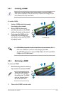
2. Conguration 2 (Mirroring) :
Eight memories population
DIMM 00 (Slot 0:Channel 0)
MCH
Branch 0
DIMM 01 (Slot 1:Channel 0)
DIMM 10 (Slot 0:Channel 1)
DIMM 11 (Slot 1:Channel 1)
DIMM 20 (Slot 0:Channel 2)
DIMM 21 (Slot 1:Channel 2)
DIMM 30 (Slot 0:Channel 3)
DIMM 31 (Slot 1:Channel 3)
Branch 1
(Mirror)