


ASUS M2V
2-29
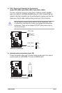
• System Power LED Lead (3-1 pin PLED)
This 3-1 pin connector connects to the system power LED. The LED
lights up when you turn on the system power, and blinks when the
system is in sleep mode.
• System Warning Speaker Lead (4-pin SPEAKER)
This 4-pin connector is for the case-mounted speaker. It allows you to
hear system beeps and warnings.
• Reset Switch Lead (2-pin RESET)
This 2-pin connector is for the case-mounted reset switch to reboot the
system without turning off the system power.
• ATX Power Switch / Soft-Off Switch Lead (2-pin PWRSW)
This connector is for the system power switch. Pressing the power
switch turns the system between ON and SLEEP, or ON and SOFT
OFF, depending on the BIOS or OS settings. Pressing the power
switch while in the ON mode for more than four seconds turns the
system OFF.
• Hard disk activity LED (2-pin IDE_LED)
This connector supplies power to the hard disk activity LED. Any read
or write activity of an IDE device causes this LED to light up.
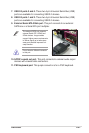
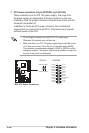
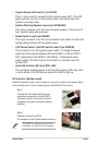
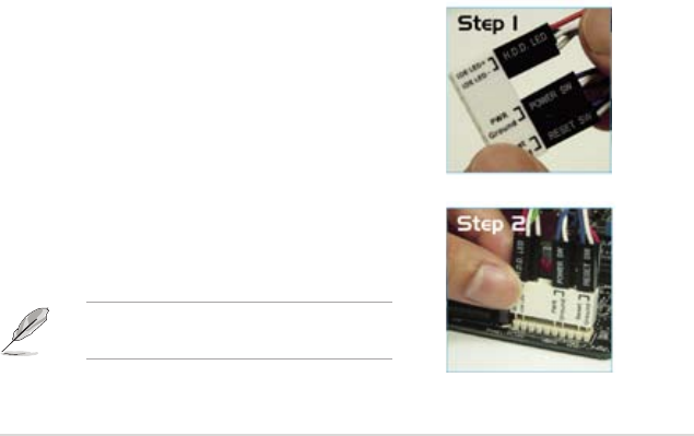
Q-Connector (System panel)
ASUS Q-Connector allows you to easily to connect the chassis front panel cables
to the motherboard. Perform these steps to install ASUS Q-Connector.
Step 1
Connect the front panel cables to their
respective connectors on the ASUS Q-
Connector. Refer to the labels on the Q-
Connector for proper connection and pin
denition.
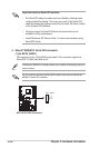
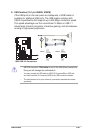
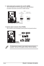
Step 2
Carefully connect the ASUS
Q-Connector to the System panel connector.
The ASUS Q-Connector ts only in one
orientation; if it doesn’t t, try reversing it.