


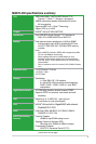
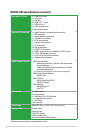
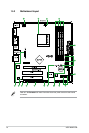
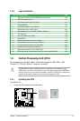
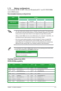
1.5.4 Layout contents
Connectors/Jumpers/Slots Page
1. ATX power connectors (24-pin EATXPWR, 8-pin ATX12V) 1-23
2. AMD CPU 940-pin Socket
1-7
3. CPU fan connector (4-pin CPU_FAN)
1-8
4. DDR2 DIMM slots
1-10
5. Serial ATA connectors (7-pin SATA1-6)
1-21
6. IDE connector (40-1 pin PRI_EIDE)
1-20
7. USB connectors (10-1 pin USB78, USB910, USB1112)
1-22
8. LPT connector
1-19
9. Clear RTC RAM (3-pin CLRTC)
1-16
10. Onboard LED 1-5
11. System panel connector (20-8 pin PANEL) 1-25
12. Floppy disk drive connector (34-1 pin FLOPPY)
1-18
13. Front panel audio connector (10-1 pin AAFP)
1-22
14. Optical drive audio connector (4-pin CD)
1-20
15. Digital audio connector (4-1 pin SPDIF_OUT)
1-19
16. Chassis and power fan connectors (3-pin CHA_FAN, 3-pin PWR_FAN)
1-24
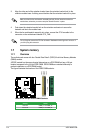
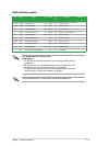
1.6 Central Processing Unit (CPU)
The motherboard comes with an AM2+ / AM2 socket designed for AMD
®
AM2+ / AM2
Phenom™ FX / Phenom / Athlon™ / Sempron™ processor.
The AM2/AM2+ socket has a different pinout from the 940-pin socket designed for the
AMD Opteron™ processor. Ensure that you use a CPU that is designed for the AM2/AM2+
socket. The CPU ts in only one correct orientation. DO NOT force the CPU into the socket
to prevent bending the connectors on the socket and damaging the CPU!
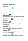
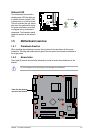
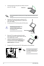
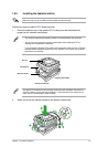
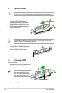
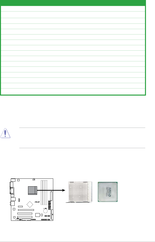
1.6.1 Installing the CPU
To install a CPU:
1. Locate the CPU socket on the motherboard.
M3N78-CM
R
M3N78-CM CPU Socket AM2+
Chapter 1: Product introduction 1-7