


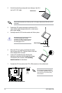
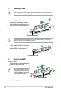
3. Align the other end of the retention bracket (near the retention bracket lock) to the
retention module base. A clicking sound denotes that the retention bracket is in place.
Make sure that the fan and heatsink assembly perfectly ts the retention mechanism
module base, otherwise you cannot snap the retention bracket in place.
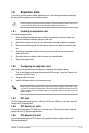
4. Push down the retention bracket lock on the retention mechanism to secure the
heatsink and fan to the module base.
5. When the fan and heatsink assembly is in place, connect the CPU fan cable to the
connector on the motherboard labeled CPU_FAN.
Do not forget to connect the CPU fan connector! Hardware monitoring errors can occur if
you fail to plug this connector.
1.7 System memory
1.7.1 Overview
The motherboard comes with four Double Data Rate 2 (DDR2) Dual Inline Memory Modules
(DIMM) sockets.
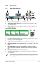
A DDR2 module has the same physical dimensions as a DDR DIMM but has a 240-pin
footprint compared to the 184-pin DDR DIMM. DDR2 DIMMs are notched differently to
prevent installation on a DDR DIMM socket.
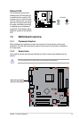
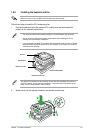
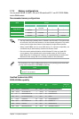
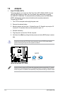
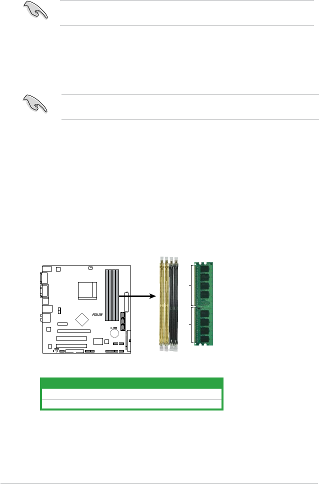
The gure illustrates the location of the DDR2 DIMM sockets:
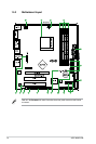
M3N78-CM
R
M3N78-CM 240-pin DDR2 DIMM Sockets
DIMM_B1
DIMM_A2
DIMM_B2
DIMM_A1
128 Pins
112 Pins
Channel Socket
Channel A DIMM_A1 and DIMM_A2
Channel B DIMM_B1 and DIMM_B2
1-10 ASUS M3N78-CM