


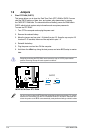
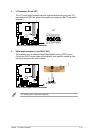
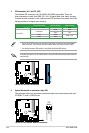
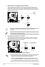
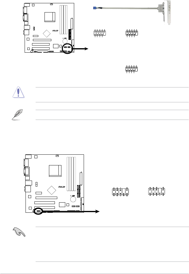
7. USB connectors (10-1 pin USB78, USB 910, USB1112)
These connectors are for USB 2.0 ports. Connect the USB module cable to any of
these connectors, then install the module to a slot opening at the back of the system
chassis. These USB connectors comply with USB 2.0 specication that supports up to
480 Mbps connection speed.
Never connect a 1394 cable to the USB connectors. Doing so will damage the
motherboard!
The USB 2.0 module is purchased separately.
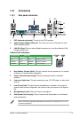
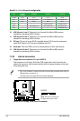
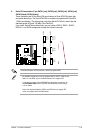
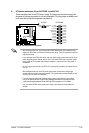
8. Front panel audio connector (10-1 pin AAFP)
This connector is for a chassis-mounted front panel audio I/O module that supports
either High Denition Audio or AC`97 audio standard. Connect one end of the front
panel audio I/O module cable to this connector.
M3N78-CM
R
M3N78-CM USB 2.0 Connectors
USB78
USB+5V
USB_P8-
USB_P8+
GND
NC
USB+5V
USB_P7-
USB_P7+
GND
1
USB910
USB+5V
USB_P10-
USB_P10+
GND
NC
USB+5V
USB_P9-
USB_P9+
GND
1
USB1112
USB+5V
USB_P12-
USB_P12+
GND
NC
USB+5V
USB_P11-
USB_P11+
GND
1
M3N78-CM
R
M3N78-CM Azalia Analog Front Panel Connector
HP_HD
MIC2_L
HP_R
HP_L
MIC2_JD
Jack_Sense
MIC2_R
PRESENSE#
AGND
AAFP
Legacy AC’97-compliant
pin definition
NC
MIC2_L
Line out_R
Line out_L
NC
NC
MIC2_R
NC
AGND
Azalia-compliant
pin definition
• We recommend that you connect a high-denition front panel audio module to this
connector to avail of the motherboard high-denition audio capability.
• If you want to connect a high-denition front panel audio module to this connector,
ensure that the Front Panel Select item in the BIOS is set to [HD Audio]; if you want to
connect an AC`97 front panel audio module to this connector, set the item to [AC97].
1-22 ASUS M3N78-CM