


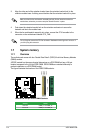
1.10.2 Internal connectors
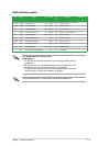
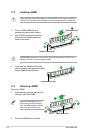
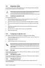
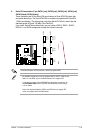
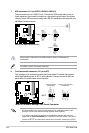
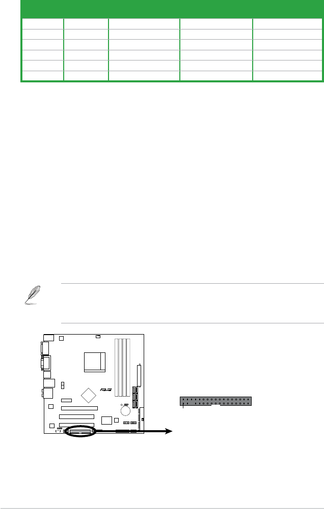
1. Floppy disk drive connector (34-1 pin FLOPPY)
This connector is for a Floppy Disk Drive (FDD) signal cable. Insert one end of the
cable to this connector, then connect the other end to the signal connector at the back
of the oppy disk drive.
• Pin 5 on the connector is removed to prevent incorrect cable connection when using an
FDD cable with a covered Pin 5.
• The Floppy Disk Drive singal cable is purchased separately.
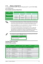
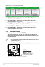
Audio 2, 4, 6, or 8-channel conguration
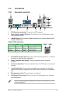
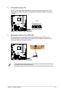
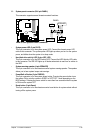
10. USB 2.0 ports 1 and 2. These two 4-pin Universal Serial Bus (USB) ports are
available for connecting USB 2.0 devices.
11. USB 2.0 ports 3 and 4. These two 4-pin Universal Serial Bus (USB) ports are
available for connecting USB 2.0 devices.
12. DVI port. This port is for any DVI-D compatible device. DVI-D can’t be converted to
output RGB Signal to CRT and isn’t compatible with DVI-I.
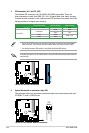
13. Serial port. This 9-pin COM1 port is for pointing devices or other serial devices.
14. USB 2.0 ports 5 and 6. These two 4-pin Universal Serial Bus (USB) ports are
available for connecting USB 2.0 devices.
Port Headset
2-channel
4-channel 6-channel 8-channel
Light Blue Line In Line In Line In Line In
Lime Line Out Front Speaker Out Front Speaker Out Front Speaker Out
Pink Mic In Mic In Mic In Mic In
Orange – – Center/Subwoofer Center/Subwoofer
Black – Rear Speaker Out Rear Speaker Out Rear Speaker Out
Gray – – – Side Speaker Out
M3N78-CM
R
M3N78-CM
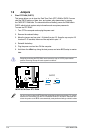
Floppy Disk Drive Connector
NOTE:
Orient the red markings on
the floppy ribbon cable to PIN 1.
PIN1
FLOPPY
1-18 ASUS M3N78-CM