


ASUS P2L97A User’s Manual 15
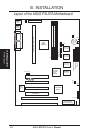
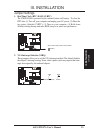
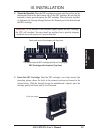
2. System Memory (DIMM)
Only Dual Inline Memory Modules (DIMM’s) can be used with this motherboard.
Four sockets are available for 3.3Volt (power level) Unbuffered Synchronous DRAMs
(SDRAM) or EDO DRAM of either 8, 16, 32, 64, or 128MB to form a memory size
between 8MB to 512MB. One side (with memory chips) of the DIMM module takes
up one Row on the motherboard.
To utilize the chipset’s Error Checking and Correction (ECC) feature, you must use
a DIMM module with 9 chips per side (standard 8 chips/side + 1 parity chip) and
make the proper settings in the BIOS Chipset Features Setup.
IMPORTANT: Memory speed setup is required through “Auto Configuration” in
BIOS Chipset Features Setup.
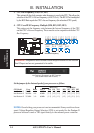
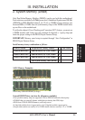
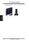
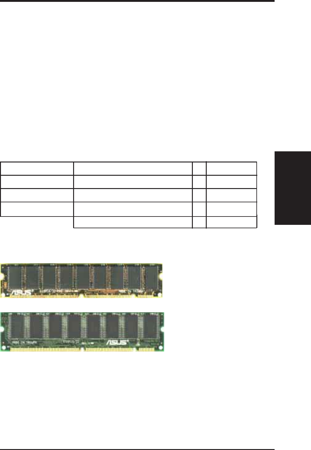
Parity EDO DIMM (9 chips)
Non-Parity SDRAM DIMM (8 chips)
General DIMM Notes: (not true for all memory modules)
• Four possible memory chips are supported: EDO or SDRAM with and without parity.
• SDRAM chips are generally thinner with higher pin density than EDO chips.
• BIOS shows EDO or SDRAM memory on bootup screen.
• 8 chip/side modules do not support parity, only 9 chip/side modules support parity.
• Single sided modules are usually 16 or 64 MB, double sided are usually 8, 32, or 128MB.
ASUS Memory Examples:
III. INSTALLATION
III. INSTALLATION
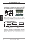
System Memory
Install memory in any combination as follows:
DIMM Location 168-pin DIMM Memory Modules Total Memory
Socket 0 (Rows 0&1) SDRAM/EDO 8, 16, 32, 64, 128MB x1
Socket 1 (Rows 2&3) SDRAM/EDO 8, 16, 32, 64, 128MB x1
Socket 2 (Rows 4&5) SDRAM/EDO 8, 16, 32, 64, 128MB x1
Total System Memory (Max 384MB) =