


ASUS P2L97A User’s Manual 25
III. INSTALLATION
Connectors
III. INSTALLATION
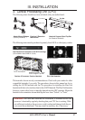
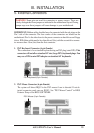
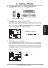
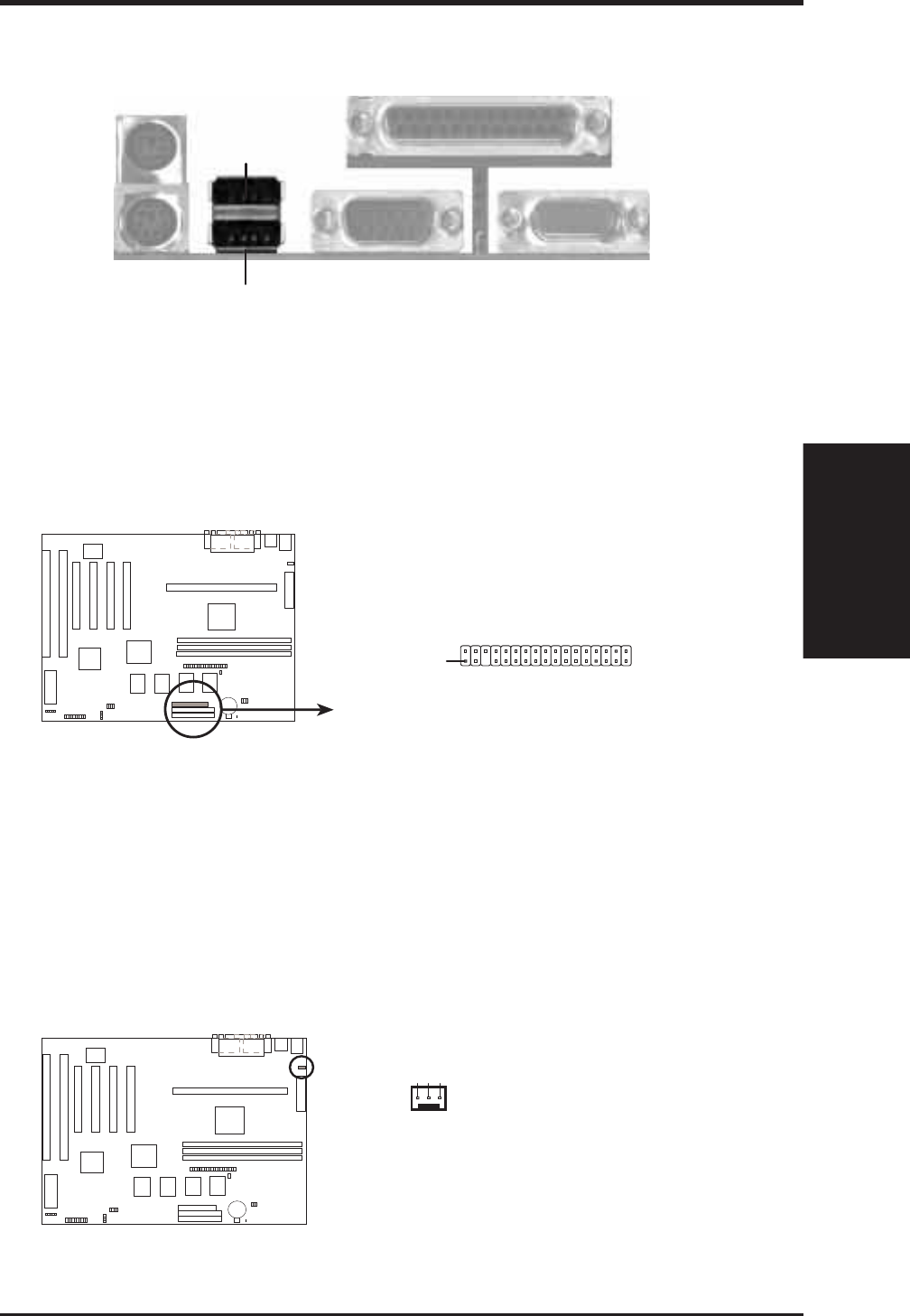
6. Universal Serial BUS Ports 1 & 2 (Two 4-pin Female Sockets)
Two USB ports are available for connecting USB devices.
Univeral Serial Bus (USB) 2
USB 1
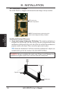
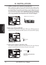
7. Floppy Disk Drive Connector (34-1pin FLOPPY)
This connector supports the provided floppy drive ribbon cable. After connect-
ing the single end to the board, connect the two plugs on the other end to the
floppy drives. (Pin 5 is removed to prevent inserting in the wrong orienta-
tion when using ribbon cables with pin 5 plugged).
Floppy Disk Drive Connector
NOTE: Orient the red stripe to Pin 1
Pin 1
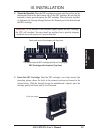
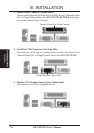
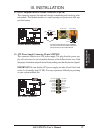
8. CPU Fan Power Lead (3-pin FAN1)
These connectors support cooling fans of 500mA (6W) or less. Orient the fans
so that the heatsink fins allow airflow to go across the onboard heatsink instead
of the expansion slots. Depending on the fan manufacturer, the wiring and plug
may be different. The red wire should be positive, while the black should be
ground. Connect the fan’s plug to the board taking into consideration the polar-
ity of the this connector.
12Volt Cooling Fan Power
CPU Fan Power
Ground
Ground
+12V