


ASUS P2L97A User’s Manual 27
III. INSTALLATION
Connectors
III. INSTALLATION
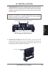
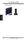
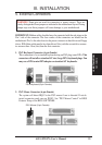
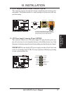
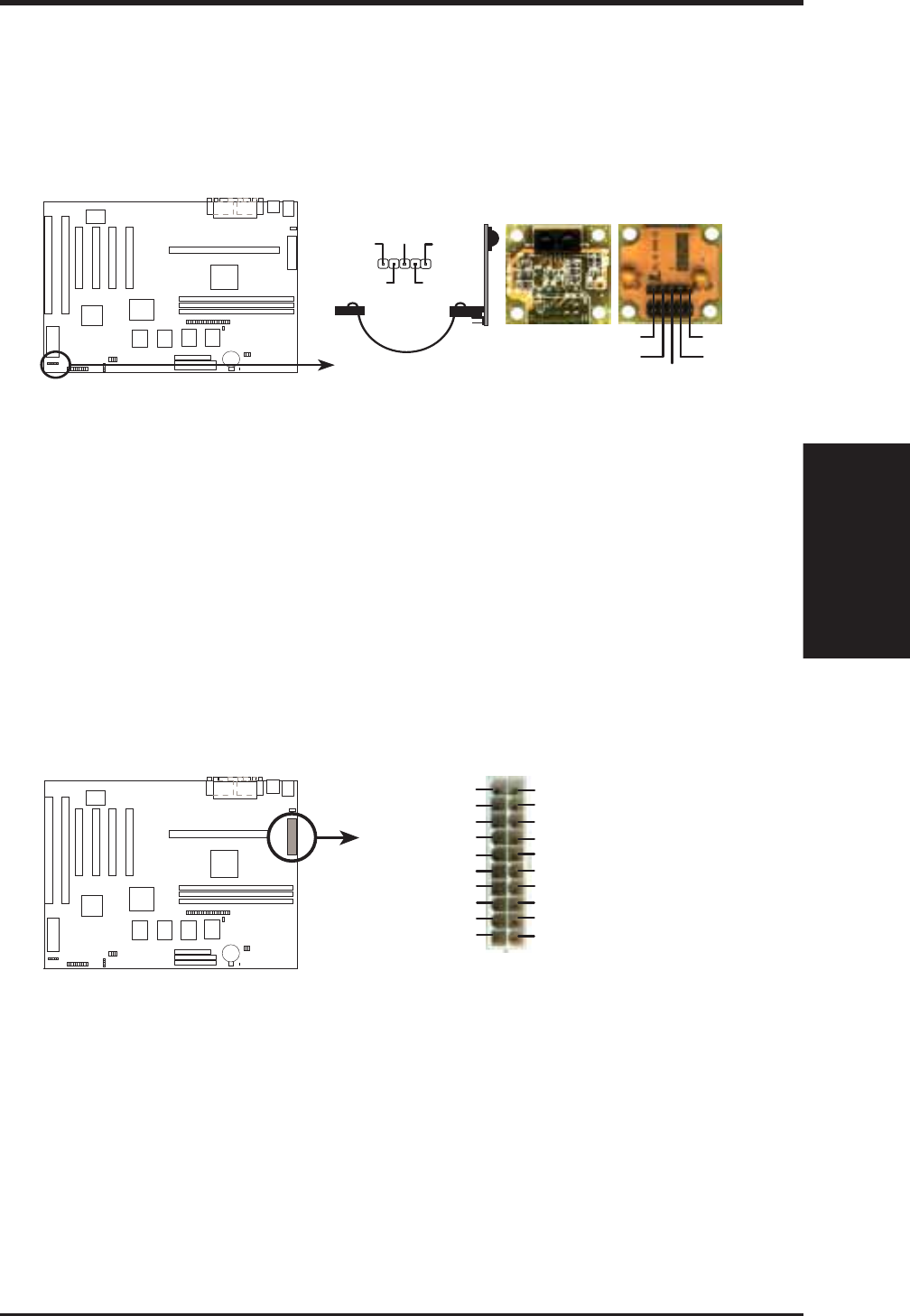
12. IrDA-Compliant Infrared Module Connector (5-pin IR)
This connector supports the optional wireless transmitting and receiving infra-
red module. This module mounts to a small opening on system cases that sup-
port this feature.
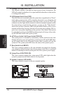
Infrared Module Connector
NC
IRTX
IRRX
+5V
Ground
Front View
+5V
IRTX
IRRX
NC
Ground
Back View
s
For the infrared feature to be available,
you must connect the optional infrared
(IrDA) module to the motherboard
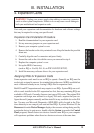
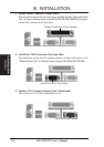
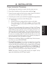
13. ATX Power Supply Connector (20-pin ATXPWR)
This connector connects to a ATX power supply. The plug from the power sup-
ply will only insert in one orientation because of the different hole sizes. Find
the proper orientation and push down firmly making sure that the pins are aligned.
IMPORTANT: Be sure that the ATX power supply can take at least 10mA load
on the 5-volt standby lead (5V SB). You may experience difficulty in powering
on your system without this.
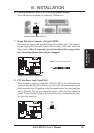
ATX Power Connector
+3.3 Volts
-12.0 Volts
Ground
Power Supply On
Ground
Ground
Ground
-5.0 Volts
+5.0 Volts
+5.0 Volts
Power Good
+12.0 Volts
+3.3 Volts
+3.3 Volts
Ground
+5.0 Volts
Ground
5.0 Volts
Ground
+5V Standby