


26 ASUS P2L97A User’s Manual
Connectors
III. INSTALLATION
III. INSTALLATION
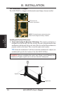
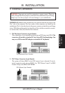
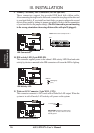
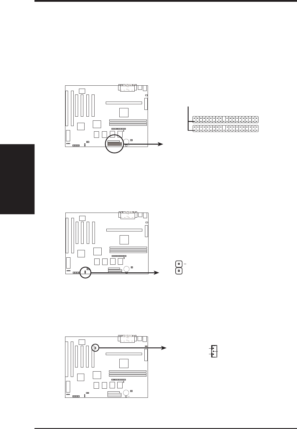
9. Primary / Secondary IDE Connectors (Two 40-1pin IDE)
These connectors support the provided IDE hard disk ribbon cable.
After connecting the single end to the board, connect the two plugs at the other end
to your hard disk(s). If you install two hard disks, you must configure the second
drive to Slave mode by setting its jumper accordingly. Refer to the documentation
of your hard disk for the jumper settings. (Pin 20 is removed to prevent inserting
in the wrong orientation when using ribbon cables with pin 20 plugged).
Primary IDE Connector
Pin 1
Secondary IDE Connector
IDE Connectors
NOTE: Orient the red stripe to Pin 1
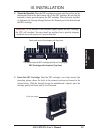
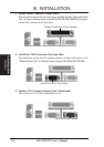
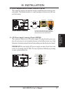
10. IDE activity LED (2-pin IDELED)
This connector supplies power to the cabinet’s IDE activity LED. Read-and-write
activity by devices connected to the IDE connectors will cause the LED to light up.
IDE Activity LED
IDELED
+
(IDE Signal)
(+5V)
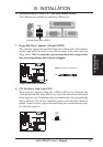
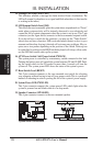
11. Wake on LAN Connector (3-pin WOL_CON)
This connector coonects to LAN cards with a Wake On LAN output. When the
system is in soft-off mode, LAN activity will power on the system.
Wake on LAN Connector
IMPORTANT: Requires an ATX power
supply with at least 720mA +5-volt
standby power
+5-Volt Standby
PME
Ground