


1-4
Chapter 1: Motherboard Information
11
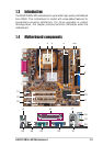
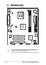
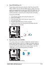
ATX 12V connector. This power connector connects the 4-pin 12V
plug from the ATX 12V power supply.
CPU Sockets. A 478-pin surface mount, Zero Insertion Force (ZIF)
socket for the Intel
®
Pentium
®
4 478/Northwood Processor with 400
MHz system bus that allows 3.2 GB/s data transfer rates.
NorthBridge Controller. This Intel Brookdale GL controller
integrates a high performance host interface for the Intel
®
Pentium
®
4 processor, a memory controller and an integrated graphics
interface.
DDR DIMM Sockets. These two 184-pin DIMM sockets support up
to 2GB using non-ECC PC2100/1600 DDR SDRAM DIMMs with
2.1GBytes/sec of transfer rate.
ATX power connector. This standard 20-pin connector connects to
an ATX 12V power supply. The power supply must have at least 1A
on the +5V standby lead (+5VSB).
Super I/O chipset. This interface provides the commonly used
Super I/O functionality. The chipset supports a high-performance
floppy disk controller for a 360K/720K/1.44M/2.88M floppy disk
drive, a PS/2 keyboard and mouse port, a multi-mode parallel port,
a game port and two serial ports.
Floppy Disk connector. This connector connects the provided
ribbon cable for the floppy disk drive. One side of the connector is
slotted to prevent incorrect insertion of the floppy disk cable.
IDE Connectors. These dual-channel bus master IDE connectors
support up to four Ultra DMA 100/66, PIO Modes 3 & 4 IDE
devices. Both the primary(blue) and secondary(black) connectors
are slotted to prevent incorrect insertion of the IDE ribbon cable.
Flash ROM. This 2Mb firmware contains the programmable BIOS
program.
South bridge controller. This Intel ICH4 FW82801DB controller
integrates the AC’97 Interface, six Universal Serial Bus 2.0, two
IDE Master/Slave controllers, the ITE 8708F Super I/O, Flash
BIOS, and PCI bus for two PCI Slots.
ASUS ASIC. This chip performs multiple system functions that
include hardware and system voltage monitoring among others.
10
1
2
3
4
5
6
7
8
9