


ASUS P4BGL-MX Motherboard
1-17
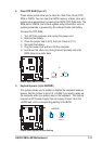
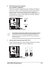
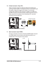
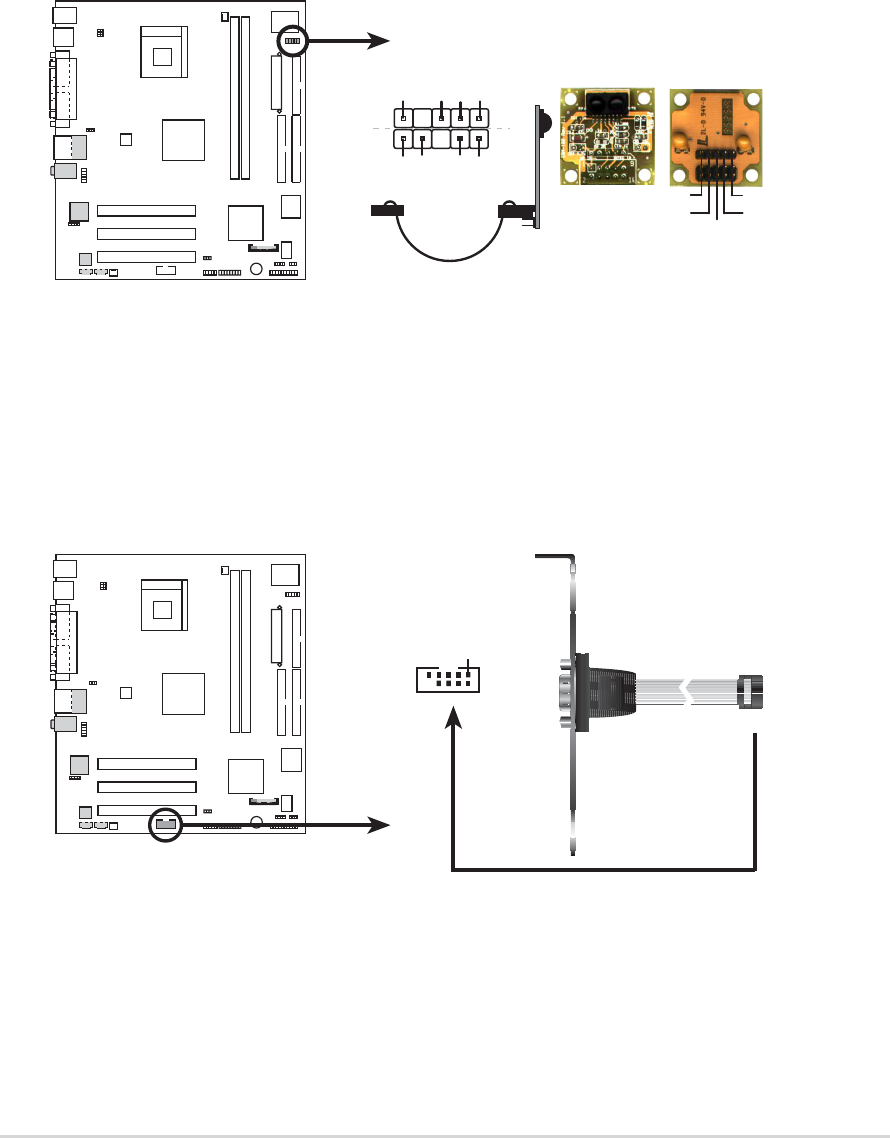
10. infrared connector (10-pin IR1)
These connectors support an optional wireless transmitting and
receiving infrared module. The module mounts to a small opening on
the system chassis that supports this feature. You must also
configure the UART2 Use As parameter in BIOS to set UART2 for
use with IR. Use the ten pins as shown in Back View and connect a
ribbon cable from the module to the motherboard IR1 connector
according to the pin definitions.
P4BGL-MX
P4BGL-MX Infrared Module Connector
Standard Infrared (SIR)
Front View Back View
+5V
IRTX
IRRX
(NC
)
GND
SIR
+5V
IRRX
IRTX
GND
IRAX
GND
CIRRX
CIR+5V
CIR
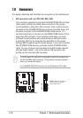
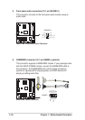
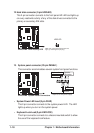
11. Serial connector (9-pin COM2 )
This 9-pin connector connects to the Serial COM2 bracket. Connect
the COM2 cable to this connector and install the bracket on an
available slot in the rear panel of the chassis.
P4BGL-MX
P4BGL-MX Serial COM2 Bracket
PIN 1
COM2