


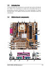
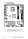
ASUS P4BGL-MX Motherboard
1-11
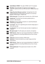
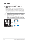
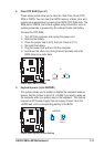
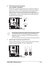
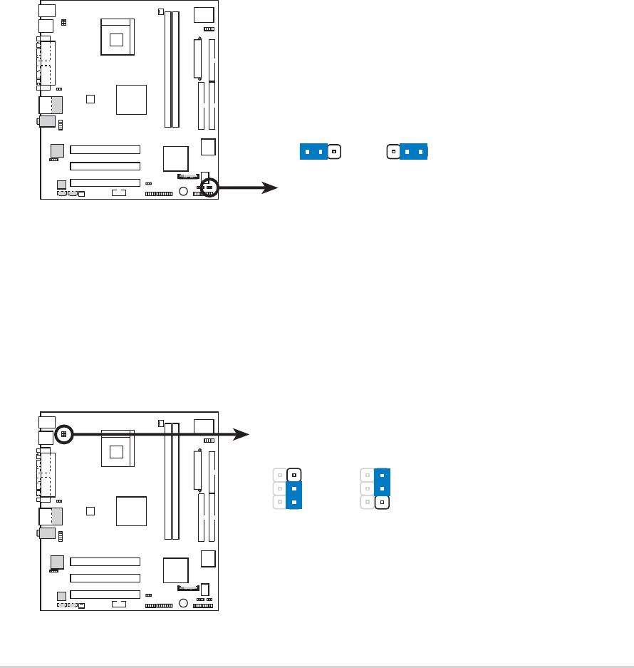
2. Clear RTC RAM (3-pin J1)
These solder points allow you to clear the Real Time Clock (RTC)
RAM in CMOS. You can clear the CMOS memory of date, time, and
system setup parameters by erasing the CMOS RTC RAM data. The
RAM data in CMOS, that include system setup information such as
system passwords, is powered by the onboard button cell battery.
To erase the RTC RAM:
1. Turn OFF the computer and unplug the power cord.
2. Remove the battery.
3. Place the jumper cap to [2-3], then put it back to [1-2]
4. Re-install the battery.
5. Plug the power cord and turn ON the computer.
6. Hold down the <Del> key during the boot process and enter
BIOS setup to re-enter data.
P4BGL-MX
2312
P4BGL-MX Clear RTC RAM
J1
Normal Clear CMOS
(Default)
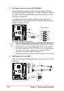
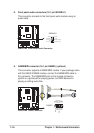
3. Keyboard power (3-pin KBPWR1)
This jumper allows you to enable or disable the keyboard wake-up
feature. Set this jumper to pins 2-3 (+5VSB) if you wish to wake up
the computer when you press a key on the keyboard . This feature
requires an ATX power supply that can supply at least 1A on the
+5VSB lead, and a corresponding setting in the BIOS.
P4BGL-MX
P4BGL-MX Keyboard Power Setting
KBPWR1
1
2
3
2
(Default)
+5V
+5VSB
(Default)