


ASUS P4BGL-MX Motherboard
1-13
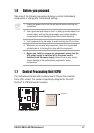
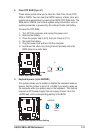
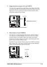
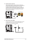
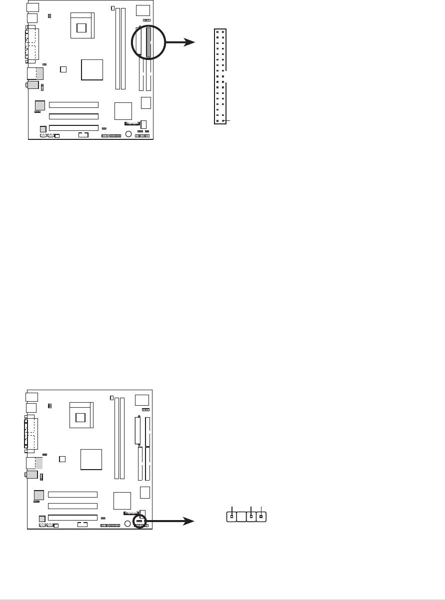
2. Floppy disk drive connector (34-1 pin FLOPPY1)
This connector supports the provided floppy drive ribbon cable. After
connecting one end to the motherboard, connect the other end to the
floppy drive. (Pin 5 is removed to prevent incorrect insertion when
using ribbon cables with pin 5 plug).
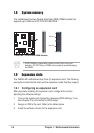
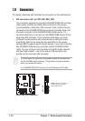
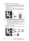
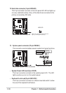
3. Chassis Alarm (4-1 pin CHASSIS1)
This lead is for a chassis designed with intrusion detection feature.
This requires an external detection mechanism such as a chassis
intrusion sensor or microswitch. When you remove any chassis
component, the sensor triggers and sends a high-level signal to this
lead to record a chassis intrusion event.
By default, the pins labeled “Chassis Signal” and “GND” are shorted
with a jumper cap. If you wish to use the chassis intrusion detection
feature, remove the jumper caps from the pins.
P4BGL-MX
NOTE: Orient the red markings o
n
the floppy ribbon cable to PIN 1.
P4BGL-MX Floppy Disk Drive Connector
PIN 1
FLOPPY1
P4BGL-MX
P4BGL-MX Chassis Alarm Lead
CHASSIS
1
+5VSB_MB
Chassis Signal
GND