


ASUS P8Z77 WS
2-3
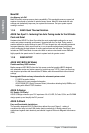
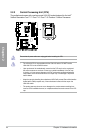
Chapter 2
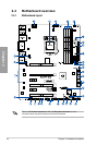
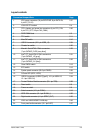
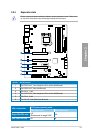
Layout contents
Connectors/Jumpers/Slots Page
1. ATX power connectors (24-pin EATXPWR, 8-pin EATX12V,
4-pin EZ_PLUG)
2-27
2. LGA1155 CPU socket 2-4
3. CPU, chassis, and power fan connectors (4-pin CPU_FAN,
4-pin CPU_OPT, 3/4 pin CHA_FAN4)
2-26
4. DDR3 DIMM slots 2-5
5. TPU switch 2-11
6. MemOK! switch 2-10
7. USB 3.0 connector (20-1 pin USB3_12) 2-24
8. Chassis fan switch 2-20
9. Marvell
®
Serial ATA 6.0 Gb/s connectors
(7-pin SATA6G_E1/E2 [navy blue])
2-23
10. Intel
®
Z77 Serial ATA 6.0 Gb/s connectors
(7-pin SATA6G_1/2 [gray])
2-21
11. Intel
®
Z77 Serial ATA 3.0 Gb/s connectors
(7-pin SATA3G_3–6 [blue])
2-22
12. Clear CMOS switch 2-13
13. EPU switch 2-12
14. System panel connector (20-8 pin PANEL) 2-29
15. Q-Code LED (LED1, LED2) 2-15
16. USB 2.0 connectors (USB10 [Type A], 10-1 pin USB1112,
10-1 pin USB1314)
2-24
17. Trusted Platform Module connector (20-1 pin TPM) 2-28
18. Reset switch 2-9
19. Power-on switch 2-9
20. Serial connector (10-1 pin COM1) 2-19
21. IEEE 1394 connector (10-1 pin IE1394_1) 2-25
22. Digital audio connector (4-1 pin SPDIF_OUT) 2-25
23. LAN1 and LAN2 WG82574 LAN chip 2-43
24. Front panel audio connector (10-1 pin AAFP) 2-27