


P/E-P55T2P4D User’s Manual 5
III. INSTALLATION
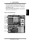
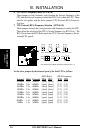
Jumpers
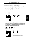
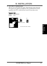
1) JP24, 25 (SMC Only) p. 7 UART 2 Selection (COM 2 / Infrared)
2) JP26, 27 (SMC Only) p. 7 ECP DMA Channel Selection (CH 3 / CH 1)
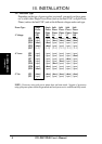
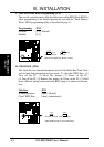
3) JP9-12, 17 p. 8 Processor Power Type (Single Plane/Split Plane)
4) JP5-8, 19-21 p. 8 Voltage Selection for Vcore
5) JP2, 3 p. 8 Voltage Selection for Vio
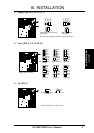
6) JP15, 16 p. 10 CPU:BUS Frequency Ratio (1.5, 2.0, 2.5, 3.0)
7) JP29, 30 p. 10 CPU External Clock (BUS) Frequency Selection
8) JP18 p. 11 APIC Dual CPU Selection (Enable / Disable)
9) JP32 p. 12 Flash ROM Boot Block Program (Enable/Disable)
10) JP34 p. 12 CMOS RAM (Operation/Clear CMOS Data)
11) JP37, 38 p. 13 PCI Slot 1 Mode Select (Master / Slave)
12) JP39 p. 13 Total Level 2 Cache Size Setting (256KB / 512KB)
Expansion Slots
1) SIMM Slots p. 14 DRAM Memory Expansion slots
2) Cache Expansion p. 16 Socket for Pipelined Burst SRAM Cache Module
3) 2 CPU ZIF Socket 7 p. 17 Sockets for Central Processing Units (CPU)
4) EISA Slots 1, 2, 3, 4 p. 18 32-bit EISA Bus Expansion slots
5) ISA Slot 1 p. 18 16-bit ISA Bus Expansion slot
6) PCI Slots 1, 2, 3 p. 18 32-bit PCI Bus Expansion slots
7) PCI 4 / MediaBus p. 20 32-bit PCI Bus Slot with MediaBus 2.0 Extension
Connectors
1) Keyboard p. 21 Keyboard connector (5-pin Female)
2) PS/2 Mouse p. 21 PS/2 Mouse connector (6-pin Block)
3) Parallel Port p. 22 Parallel Port connector (26-pin Block)
4) Serial Port p. 22 Serial Port COM1 & COM2 (10-pin Blocks)
5) Floppy Drive p. 23 Floppy Drive connector (34-pin Block)
6) Primary/Second. IDE p. 23 Primary/Secondary IDE connectors (40-pin Blocks)
7) Board Power Input p. 24 Motherboard Power connector (12-pin Block)
8) IDE LED p. 24 IDE LED activity light
9) Turbo/Power (CON3) p. 25 Turbo LED/Power LED (2-pins)
10) SMI Switch (CON3) p. 25 SMI Switch lead (2-pins)
11) Reset Switch (CON3) p. 25 Reset Switch lead (2-pins)
12) Key Lock (CON3) p. 25 Keyboard Lock Switch lead (5-pins)
13) Speaker (CON3) p. 25 Speaker connector (4-pins)
14) FAN CN 1 & 2 p. 26 CPU 12V Cooling Fan connector
15) IR CON p. 26 Infrared Port Module connector
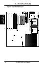
(Map of Board)
III. INSTALLATION