


Chapter 1: System introductionChapter 1: System introduction
Chapter 1: System introductionChapter 1: System introduction
Chapter 1: System introduction
1-41-4
1-41-4
1-4
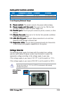
Refer to the audio configuration table on the next page for the function
of the audio ports in 2, 4, or 6-channel configuration.
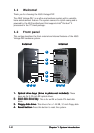
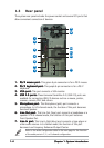
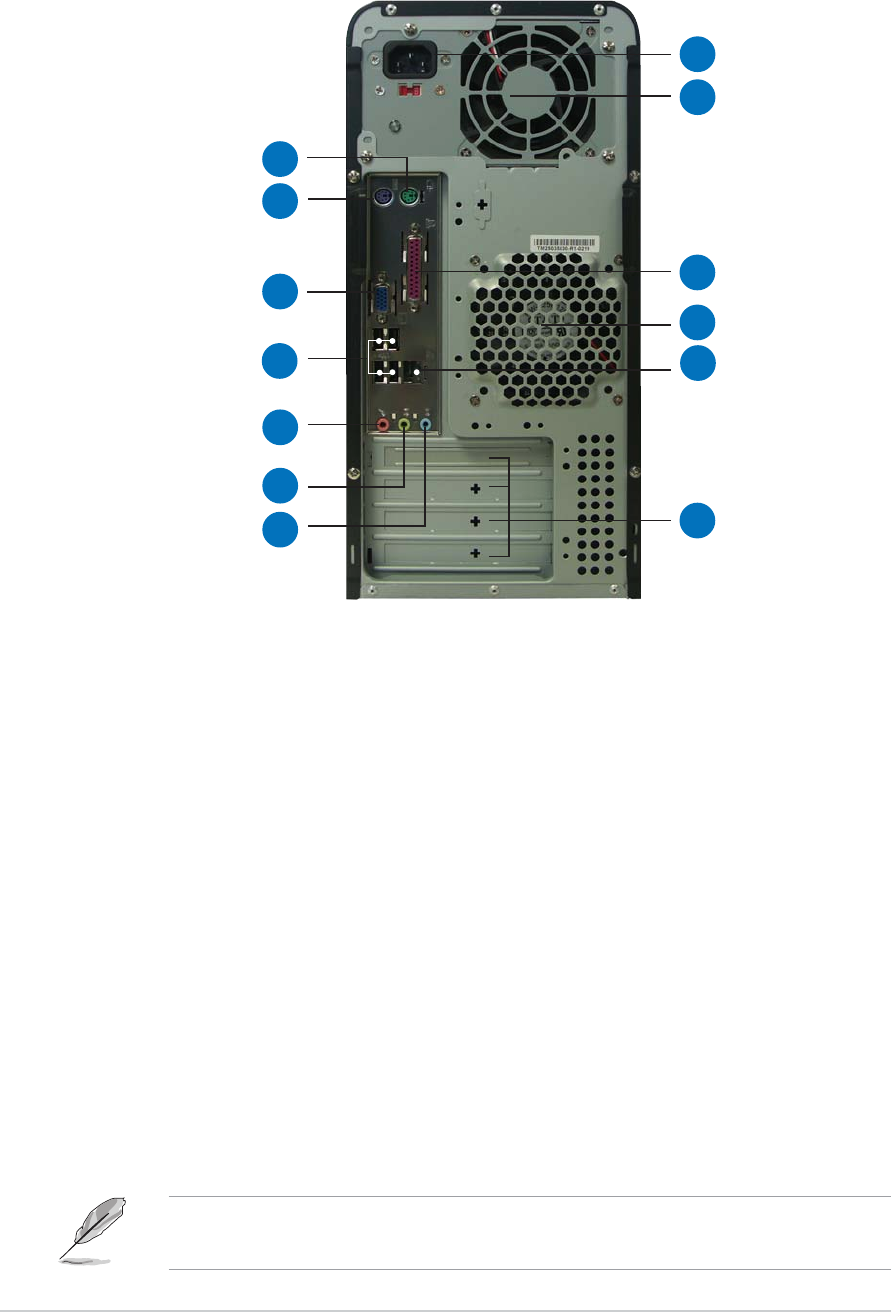
1.3 Rear panel
The system rear panel includes the power socket and several I/O ports that
allow convenient connection of devices.
11
11
1
1.1.
1.1.
1.
PS/2 mouse port. PS/2 mouse port.
PS/2 mouse port. PS/2 mouse port.
PS/2 mouse port. This green 6-pin connector is for a PS/2 mouse.
2.2.
2.2.
2.
PS/2 keyboard port.PS/2 keyboard port.
PS/2 keyboard port.PS/2 keyboard port.
PS/2 keyboard port. This purple 6-pin connector is for a PS/2
keyboard.
3.3.
3.3.
3.
VGA port.VGA port.
VGA port.VGA port.
VGA port. This port connects a VGA monitor.
4.4.
4.4.
4.
USB 2.0 ports.USB 2.0 ports.
USB 2.0 ports.USB 2.0 ports.
USB 2.0 ports. These Universal Serial Bus 2.0 (USB 2.0) ports are
available for connecting USB 2.0 devices such as a mouse, printer,
scanner, camera, PDA, and others.
5.5.
5.5.
5.
Microphone port. Microphone port.
Microphone port. Microphone port.
Microphone port. This Microphone (pink) port connects a
microphone. In 4/6-channel mode, the function of this port becomes
Surround Speaker.
6.6.
6.6.
6.
Line Out port. Line Out port.
Line Out port. Line Out port.
Line Out port. This Line Out (lime) port connects a headphone or a
speaker. In 4/6-channel mode, the function of this port becomes
Front Speaker Out.
7.7.
7.7.
7.
Line In port.Line In port.
Line In port.Line In port.
Line In port. This Line In (light blue) port connects a tape player or
other audio sources. In 6-channel mode, the function of this port
becomes Low Frequency Enhanced Output/Center.
22
22
2
33
33
3
44
44
4
55
55
5
88
88
8
99
99
9
1010
1010
10
1111
1111
11
1212
1212
12
1313
1313
13
66
66
6
77
77
7