


4-64-6
4-64-6
4-6
Chapter 4: Motherboard informationChapter 4: Motherboard information
Chapter 4: Motherboard informationChapter 4: Motherboard information
Chapter 4: Motherboard information
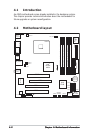
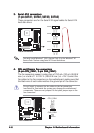
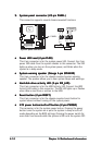
4.4.
4.4.
4.
CPU and Chassis Fan connectorsCPU and Chassis Fan connectors
CPU and Chassis Fan connectorsCPU and Chassis Fan connectors
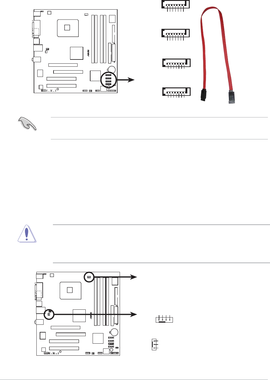
CPU and Chassis Fan connectors
(4-pin CPU_FAN1, 3-pin CHA_FAN1)(4-pin CPU_FAN1, 3-pin CHA_FAN1)
(4-pin CPU_FAN1, 3-pin CHA_FAN1)(4-pin CPU_FAN1, 3-pin CHA_FAN1)
(4-pin CPU_FAN1, 3-pin CHA_FAN1)
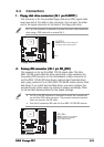
The fan connectors support cooling fans of 350 mA~740 mA (8.88 W
max.) or a total of 1 A~2.22 A (26.64 W max.) at +12V. Connect the
fan cables to the fan connectors on the motherboard, making sure that
the black wire of each cable matches the ground pin of the connector.
Do not forget to connect the fan cables to the fan connectors.
Insufficient air flow inside the system may damage the motherboard
components. These are not jumpers! Do not place jumper caps on the
fan connectors!
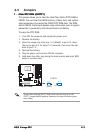
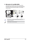
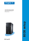
3.3.
3.3.
3.
Serial ATA connectorsSerial ATA connectors
Serial ATA connectorsSerial ATA connectors
Serial ATA connectors
(7-pin SATA1, SATA2, SATA3, SATA4)(7-pin SATA1, SATA2, SATA3, SATA4)
(7-pin SATA1, SATA2, SATA3, SATA4)(7-pin SATA1, SATA2, SATA3, SATA4)
(7-pin SATA1, SATA2, SATA3, SATA4)
These connectors are for the Serial ATA signal cables for Serial ATA
hard disk drives.
You must install Windows
®
2000 Service Pack 4 or the Windows
®
XP
Service Pack1 before using Serial ATA hard disk drives.
®
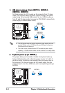
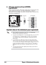
SATA connectors
SATA1
GND
RSATA_TXP1
RSATA_TXN1
GND
RSATA_RXP1
RSATA_RXN1
GND
SATA4
GND
RSATA_TXP4
RSATA_TXN4
GND
RSATA_RXP4
RSATA_RXN4
GND
SATA3
GND
RSATA_TXP3
RSATA_TXN3
GND
RSATA_RXP3
RSATA_RXN3
GND
SATA2
GND
RSATA_TXP2
RSATA_TXN2
GND
RSATA_RXP2
RSATA_RXN2
GND
®
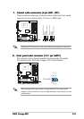
Fan connectors
CPU_FAN1
CHA_FAN1
GND
CPU FAN PWR
CPU FAN IN
CPU FAN PWM
GND
Rotation
+12V