


2-222-22
2-222-22
2-22
Chapter 2: Basic installationChapter 2: Basic installation
Chapter 2: Basic installationChapter 2: Basic installation
Chapter 2: Basic installation
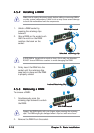
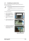
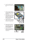
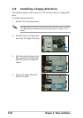
7. Connect a power cable from
the power supply to the power
connector at the back of the
optical drive.
8. Connect the black interface of
the IDE ribbon cable to the IDE
interface at the back of the
optical drive, matching the red
stripe on the cable with Pin 1
on the IDE interface.
9. Connect one end of the audio
cable to the 4-pin connector at
the back of the optical drive.
Red stripe to pin 1Red stripe to pin 1
Red stripe to pin 1Red stripe to pin 1
Red stripe to pin 1
IDE ribbon cableIDE ribbon cable
IDE ribbon cableIDE ribbon cable
IDE ribbon cable
Power cable (P1)Power cable (P1)
Power cable (P1)Power cable (P1)
Power cable (P1)
Audio cableAudio cable
Audio cableAudio cable
Audio cable
7
8
9
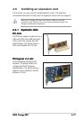
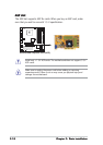
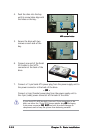
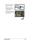
10. Connect the blue interface of
the IDE ribbon cable to the
primary IDE connector (blue
connector labeled PRI_IDE1)
on the motherboard.
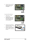
11. Connect the other end of the
audio cable to the black 4-pin
connector labeled CD1 on the
motherboard.
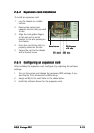
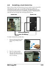
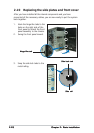
6. Secure the optical drive with
two screws on each side of the
bay.
6 6
CD1 connectorCD1 connector
CD1 connectorCD1 connector
CD1 connector
PRI_IDE1PRI_IDE1
PRI_IDE1PRI_IDE1
PRI_IDE1
connectorconnector
connectorconnector
connector