


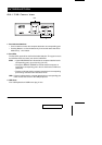
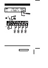

1. Console Audio Jacks
The cables from your microphone and speakers plug in here. Each jack is
marked with an appropriate icon to indicate itself.
2. USB Peripheral Section
USB peripherals (printers, scanners, etc.) can plug into any available port.
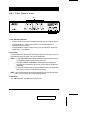
3. Firmware Upgrade Section
M Firmware Upgrade Recovery Switch
During normal operation and while performing a fimware upgrade, this
switch should be in the NORMAL position. See p. 25 for details about the
use of this switch.
M Firmware Upgrade Port
The Firmware Upgrade Cable that transfers the firmware upgrade data
from the administrator’s computer to the CS-1732 / CS-1734 plugs into
this RJ-11 connector. See p. 19 for firmware upgrading details.
4. Power Jack
If you choose to use external power, the power adapter cable plugs into this
jack.
Note: Use of a power adapter (DC 5V) is optional, and requires a separate
purchase.
5. Monitor Port
The video cable from your monitor plugs in here.
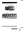
6. CPU Port Section
The cables that link the switch to your computers plug in here. Each CPU
port is comprised of a microphone jack, speaker jack, and KVM data
connector.
Note: The shape of these 15-pin connectors has been specifically modified
so that only KVM cables designed to work with this switch can plug in
(see the Cables section on p. 3, for details). Do NOT attempt to use
ordinary 15 pin VGA connector cables to link these ports to the
computers.
2003-07-17
CS-1732 / CS-1734 User Manual 7