Chapter 1. Introduction
7
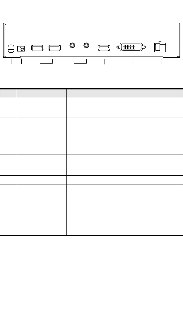
CE680 / CE690 (Local / Remote Unit) Rear View
No. Component Description
1 Cable Tie Slot If you want to use a cable tie to gather the cables
together, you can run it through this slot to attach it to
the unit.
2 Power Jack Connect the power adapter into this jack.
3 USB Ports (for
Keyboard / Mouse)
The USB cable for your keyboard / mouse plugs in
here.
4 Audio Ports
(Speakers / Mic)
These mini stereo ports are for the speakers (green)
and microphone (pink).
5 USB Port (for Touch
Panel)
Connect a USB touchscreen panel device to this port.
Note: Only generic touch panel devices (no driver
installation required) are supported by this port.
6 DVI Output port Connect a compatible monitor to this DVI serial port.
7 Optical In/Out Port The fiber optic cable that connects the Local and
Remote units plugs in here.
The optical fiber modules are color-coded accordingly:
CE680L – Blue
CE680R – Yellow
CE690L – Purple
CE690R – White
2
4
5
6
3
7
1


