


Document No. 10-300077, Issue 2 1-3
Introduction
■ The Power System
■ The M8000R-SUP Supervisor Module
■ Media Modules
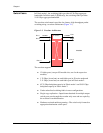
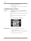
Avaya P580 Multiservice Switch Chassis
The Avaya P580 Multiservice Switch chassis consists of:
■ Seven slots (1 slot for the supervisor module and six payload slots
for media modules)
■ Fan Tray
■ Up to three power supplies
■ A 13x13 crossbar switch fabric
Slots There are seven slots in the P580 chassis. Slot 1 is dedicated for a
supervisor module and the remaining six are payload slots. If a redundant
supervisor is used in the chassis, it must be inserted in slot 2.
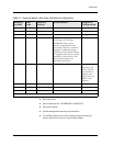
Ports The P580 chassis configured with 50-series modules provides support for:
■ Up to 120 10/100BASE-TX ports (RJ-45 connector, autosensing)
■ Up to 288 10/100BASE-TX ports (Telco connector, autosensing)
■ Up to 60 100BASE-FX ports
■ Up to 24 gigabit-speed Ethernet ports
The P580 chassis configured with 80-series modules provides support for:
■ Up to 144 10/100BASE-TX ports (RJ-45 connector, autosensing)
■ Up to 288 10/100BASE-TX ports (Telco connector, autosensing)
■ Up to 144 100BASE-FX ports (MT-RJ connector)
■ Up to 48 gigabit-speed Ethernet ports
Fan Tray There are two fan assemblies in the chassis. One fan assembly is located on
the left side of the chassis to provide air flow to the media modules. This fan
assembly is hot-swappable. The other fan assembly is located in the rear of
the chassis to provide air flow to the switch fabric. This fan assembly is not
field replaceable.