Chapter 2 Installation
4. Place the P117F(R) or other P110 switches in the stack. The P110 NMA must be
in the top switch of the stack.
To ensure proper ventilation, ensure that all empty P110 NMA slots in the
stack are closed.
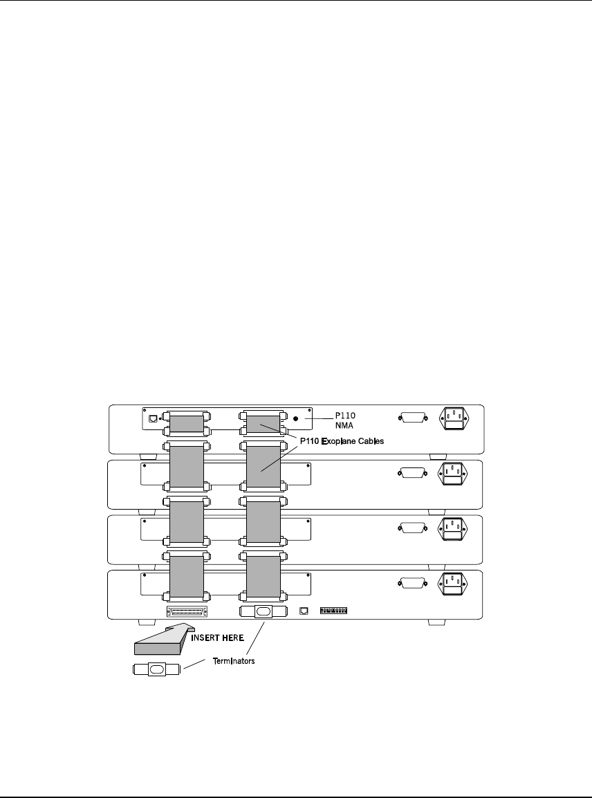
5. Connect P110 switches using the supplied P110 Exoplane cables, as shown in
Figure 2. A switch connects to its upper neighbor through two Exoplane
cables, and to its lower neighbor through another two Exoplane cables. Make
sure you securely fasten the cables to the connectors.
Cabling Requirements:
• For correct operation, the P110 Exoplane must be fully connected, with all
units powered up. In a stack configuration, the P110 NMA must be installed
and connected to the P110 Exoplane.
Failure to observe this requirement will cause the P110 units to block all traffic
on attached stations and segments.
• When using the P114T or P114F in the stack, make sure all switches in the
stack are connected using P110 Exoplane cables (part number 108362203, with
white connectors and marked C/S:B) of the type supplied with the new P110
switch. Extra cables can be ordered from your local Avaya representative.
Figure 2 Rear view of a P110 stack, showing how the switches are linked via the P110
Exoplane cables. A P110 NMA resides in the uppermost switch.
6. Two terminators are supplied with the P110 NMA. Insert the two terminators
into the lowest two connectors at the bottom of the stack, as shown in Figure 2.
7. Turn on the mains power to the stack, by individually switching on each
switch.
8. Connect the cables to the front panel ports.
P117F(R) Stackable Switch Installation Guide 7


