


Chapter 2: Installation 9
Connecting the DSR1024 Switch Hardware
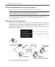
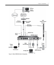
To connect and power on your DSR1024 switch:
1. Power off the target devices that will be part of your DSR1024 switching system. Locate the
power cord that came with the DSR1024 switch. Plug one end into the power socket on the
back panel of the DSR1024 switch. Plug the other end into a grounded AC wall outlet.
WARNING: To reduce the risk of electric shock or damage to your equipment:
• Do not disable the power cord grounding plug. The grounding plug is an important safety feature.
• Plug the power cord into a grounded (earthed) outlet that is easily accessible at all times.
• Disconnect the power from the switch by unplugging the power cord from either the electrical outlet or
the appliance.
2. Plug the VGA monitor and PS/2 keyboard and mouse cables into the corresponding DSR1024
switch ports. You must install both a keyboard and mouse on the local port, or the keyboard
will not initialize properly.
3. Plug one end of a CAT 5 patch cable (4-pair, up to 10 meters) into the DSRIQ port and plug
the other end into the RJ-45 connector of a DSRIQ module.
4. Plug the DSRIQ module into the corresponding ports on the back panel of the target server.
See the
To connect a DSRIQ module to a server procedure on page 10 and the To connect a
DSRIQ module to a serial device procedure on page 10 for more information.
5. Plug a CAT 5 patch cable from your Ethernet network into the LAN port on the back of the
DSR1024 switch. Network users will access the DSR1024 switch through this port.
6. (Optional) The DSR1024 switch can also be accessed using a ITU V.92, V.90 or V.34-
compatible modem. Plug the included ribbon cable into the MODEM port on the back of your
DSR1024 switch. Plug the other end into the RJ-45 to DB-9 adaptor and plug the adaptor into
the connector on the modem.
NOTE: Using a modem connection instead of a LAN connection will limit the performance capability of your
DSR1024 switch.
7. (Optional) Plug one end of the cable supplied with the SPC power control device into the SPC
port on the DSR1024 switch and plug the other end into an SPC device. Plug the power cord
from the target server into the SPC device power outlets. Plug the SPC device into an
appropriate AC wall outlet.
8. If you will be configuring the DSR switch using the console menu interface, connect a terminal
or PC running terminal emulation software (such as HyperTerminal
®
) to the SETUP port on
the back panel of the DSR1024 switch using the suppliedcable. Set the terminal to 9600 bits
per second (bps), 8 bits, 1 stop bit, no parity and no flow control.