


10 DSR Installer/User Guide
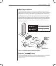
Additional items needed
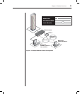
The following are additional items needed to use your DSR1021 switch:
• One DSRIQ module per server or DSRIQ-SRL module per serial device
• One CAT 5 patch cable per server or serial device (4-pair UTP, up to
10 meters)
• DSR software
• V.34, V.90 or V.92-compatible modem and cables (for optional
modem connection)
Verification of Internet/server connections
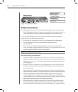
DSR switch
The front panel of the DSR1021 switch features two LEDs indicating the
Ethernet connection. The top green LED is the Link indicator. It will
illuminate when a valid connection to the network is established and blink
when there is activity on the port. The lower amber LED, labeled 100M, will
indicate that you are communicating at the 100 Mb rate when using an
Ethernet connection.
Additionally, there are two LEDs above each port number on the front of your
DSR1021 switch: one green and one amber. The green LED will illuminate
when the attached system is powered. The amber LED will illuminate when
that port is selected.
DSRIQ modules
PS/2, Sun and USB DSRIQ modules are available for attaching computers to
your DSR switch.
The DSRIQ-SRL serial module is used to connect serial devices to your DSR
switch and features two green LEDs: a POWER LED and a STATUS LED.
The POWER LED indicates that the attached server is powered. The STATUS
LED indicates that a valid UTP connection has been made to a DSR switch.
The DSRIQ-SRL module prevents a serial break from the attached device if
the module loses power. However, a user can generate a serial break with the
attached device by pressing Alt-B in the Terminal Applications menu.