


Documentation Number 232OPSDA1397 Manual 7
B&B Electronics -- PO Box 1040 -- Ottawa, IL 61350
PH (815) 433-5100 -- FAX (815) 433-5105
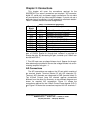
Digital I/O Connections
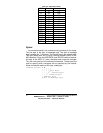
The digital I/O connections are made on the I/O port, which
consists of terminal blocks. Table 2.1 shows the terminal block
assignments.
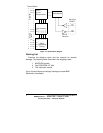
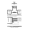
Digital Input
Terminal block 7 is the digital input line. This input is CMOS/TTL
compatible and can handle voltage from -30VDC to 30VDC. If a
digital input is from -30VDC to 1.0VDC, the state will be read as a
“0” (LOW). If a digital input is from 2.0VDC to 30VDC, the state will
be read as a “1” (HIGH). If the digital input is not used, it should be
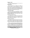
connected to GND. Figure 2.3 show the connections required for the
digital input.
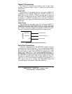
Digital Output
Terminal Block 6 is the digital output line. This line is CMOS/TTL
compatible. When the digital output is set to “0” (LOW), the output
voltage will be between 0 and 0.6VDC. When the digital output is set
to “1” (HIGH), the output voltage will be between 4.3VDC to 5.0VDC.
Figure 2.3 shows the connections required for the digital output.
Figure 2.3: Digital I/O Required Connections
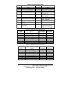
Serial Port Connections
In order to communicate with the 232OPSDA module it must be
connected to an RS-232 serial port. The unit automatically detects
baud rates from 1,200 to 9,600. A data format of 8 data bits, 1 stop
bit and no parity is used. The 232OPSDA is configured as a DCE
device (See Table 2.2). If your communications equipment is
configured as a DTE device, such as a standard IBM PC serial port,
the 232OPSDA should be connected using a “straight through” DB-
25 cable or a standard DB-9 to DB-25 cable adapter as shown in
Table 2.3. If your communications equipment is configured as a
DCE device, such as a modem, the 232OPSDA should be
connected using a “null modem” cable (See Table 2.4).
0 to 5VDC Output
-30VDC to 30VDC Inpu
t
To Device GND
2
3
2
O
P
S
D
A
GND
Digital Input
TB 7
TB 8
Digital Output
TB 6