


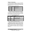

24 Documentation Number 232OPSDA1397 Manual
B&B Electronics -- PO Box 1040 -- Ottawa, IL 61350
PH (815) 433-5100 -- FAX (815) 433-5105
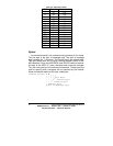
Step 5 - Repeat Step 3 and 4 until each channel has been
completed.
Step 6 - The various A/D channels have signal conditioning, so
mathematical manipulation of the voltage read will have to be
performed. See Chapter 4 for the equations.
Example 5.1 - Read A/D channels 1 and 0
gain0 = 23.064
gain1 = 1!
channel = 1
Command$ = “!0RA” + CHR$(channel)
Print #1, Command$;
‘ Get the value of channel 1
MSB$ = INPUT$ (1, #1)
LSB$ = INPUT (1, #1)
ad1 = (ASC(MSB$) * 256) + ACS(LSB$)
reading1 = 5! * ad1 / (gain1 * 4095!)
‘ Get the value of channel 0
MSB$ = INPUT$ (1, #1)
LSB$ = INPUT$ (1, #1)
ad0 = (ASC(MSB$) * 256) + ACS(LSB$)
reading0 = (((ad0 * 1000!) / 4095!) * 5!) / (10!
*
gain0)
The value of reading1 is the result of the A/D conversion on channel
1. The value of reading0 is the result of the A/D conversion on
channel 0.
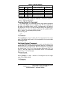
Read Digital I/O Command
The Read Digital I/O command returns a byte which represents
the states of the digital input and digital output. Bit 0 corresponds to
the state of digital output. Bit 3 corresponds to the state of digital
input. If a bit is a 0 then the digital state of that digital I/O is LOW. If
a bit is a 1 then the digital state of the I/O is HIGH.