


16 Documentation Number 232OPSDA1397 Manual
B&B Electronics -- PO Box 1040 -- Ottawa, IL 61350
PH (815) 433-5100 -- FAX (815) 433-5105
inverting amplifier, remove R15 and calculate values for R13 and
R14 using the equation below.
Gain
V
Vin
R13
R
14
==+
0
1
NOTE: V
0
is the voltage read by the A/D converter chip, and Vin is
the voltage at TB1. R13 and R14 should be chosen so that V
0
does
not exceed 5.00VDC.
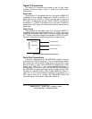
0 to 10VDC A/D Input
The 232OPSDA contains one A/D input than is capable of
handling voltages between 0VDC and 10VDC. This channel is A/D 3
and is located on Terminal Block 3. The gain of the signal
conditioning circuitry for this channel is 0.5. If 10VDC is applied to
Terminal Block 3, the A/D Converter chip will read 5.00V. The input
resistance of this channel is 200KΩ, so the driving source
impedance should be less than 1KΩ to minimize voltage division
error.
4-20mA Current Loop A/D Input
The 232OPSDA has one A/D channel capable of monitoring the
loop current in a 4-20mA analog current loop. See figure B.1 in
Appendix B for a circuit schematic. A 10Ω resistor is connected
between TB 0 and GND inside the 232OPSDA. The voltage drop
across this resistor is proportional to the current in the current loop.
With the original configuration, the following equation can be used to
convert the voltage read by the A/D converter chip to the actual
current in the loop. The value 23.064 is the gain of the signal
conditioning circuitry
()
LoopCurrent mA
AD
=
×
×
1000
23064 10
0
. Ω
NOTE: AD
0
is the voltage read by the A/D converter chip. This
voltage is between 0 and 5.00VDC.