


Documentation Number 232OPSDA1397 Manual 11
B&B Electronics -- PO Box 1040 -- Ottawa, IL 61350
PH (815) 433-5100 -- FAX (815) 433-5105
Chapter 3: Commands
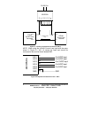
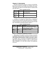
Only three commands are required to operate the 232OPSDA:
the read A/D command, read digital I/O command, and the set
digital output command. The command string consists of four bytes.
The read A/D and digital I/O commands require an additional data
byte. See Table 3.1.
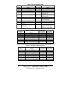
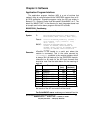
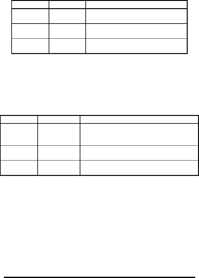
Table 3.1: 232OPSDA Commands
NOTE: Each {…} represents one byte.
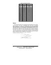
In addition to the commands mentioned above, an extended set
of commands are provided that support bit-error identification.
These commands use the “#” character in place of the “!” character,
and the compliment of the data byte must be sent after the data
byte. The extended commands are shown in table 3.2.
Table 3.1: 232OPSDA Commands
NOTE: ~{…} represents the complement of one byte.
Before going into the specifics of each command, it is important
to understand that a byte has a value from 0 to 255 and can be
represented in decimal (0 to 255), hexadecimal (00 to FF), or by an
ASCII character. The commands in Table 3.1 are shown in ASCII,
for example: “!0RD”. The decimal and hexadecimal equivalents of
some ASCII characters are shown in Table 3.2. Notice that the
ASCII representation of the character “0” does not have a value of 0.
Refer to Appendix A for more ASCII, decimal, and hexadecimal
equivalents.
Function Command Response
Read A/D
Channels
!0RA{#} {ch#msb}{ch#lsb}{ch(#-1)msb}…
{ch0msb}{ch0lsb}
Read
Digital I/O
!0RD {I/O states}
Set Digital
Output
!0SO{#} no response
Function Command Response
Read A/D
Channels
#0RA{#}~{#} {ch#msb}~{ch#msb}{ch#lsb}{ch#lsb}
{ch(#-1)msb}~{ch(#-1)msb}….{ch0msb}
~{ch0msb}{ch0lsb}~{ch0lsb}
Read
Digital I/O
#0RD {I/O states}~{I/O states}
Set Digital
Output
#0SO{#}~{#} no response