


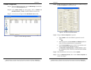
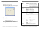
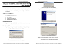

Installing the VLINX ESP Software
Manual Documentation Number: ESP904-0504 Chapter 2 13
B&B Electronics Mfg Co Inc – 707 Dayton Rd - PO Box 1040 - Ottawa IL 61350 - Ph 815-433-5100 - Fax 815-433-5104 – www.bb-elec.com
B&B Electronics Ltd – Westlink Commercial Park – Oranmore, Galway, Ireland – Ph +353 91-792444 – Fax +353 91-792445 – www.bb-europe.com
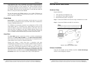
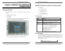
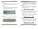
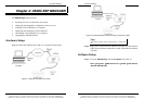
Power Connector
Plug the ultra-miniature phone plug from the included power supply into the
power jack and then plug the supply in. When power is applied the Red
power light will illuminate. The tip of the power plug is positive; the sleeve
is negative.
Reset Button
This switch resets the unit, similar to the effect of removing/applying power.
The Reset switch is recessed to avoid accidental operation. To reset the unit,
insert a small plastic tool, press lightly and hold for 3 seconds. The Link and
Ready lights will go out and then come back on.
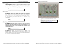
RJ-45 Receptacl
e
Power Connection
Reset
Figure 8. Top View of the ESP904
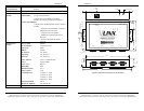
Serial Ports
The ESP904 has four serial ports, each configurable through software as RS-
232, RS-422 or RS-485 interfaces. The connectors are DTE DB-9M.
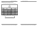
Serial Port
4 3 2 1
Figure 9. The ESP904 Serial Port Connectors
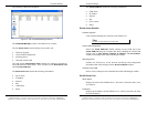
Installing the VLINX ESP Software
14 Chapter 2 Manual Documentation Number: ESP904-0504
B&B Electronics Mfg Co Inc – 707 Dayton Rd - PO Box 1040 - Ottawa IL 61350 - Ph 815-433-5100 - Fax 815-433-5104 – www.bb-elec.com
B&B Electronics Ltd – Westlink Commercial Park – Oranmore, Galway, Ireland – Ph +353 91-792444 – Fax +353 91-792445 – www.bb-europe.com
Serial Port Operational Modes
Using the ESP Manager or the Console Mode Configuration Menu each
serial port can independently be configured as
RS-232 Mode, RS422 Mode
or
RS-485 Mode. Port 1 of the ESP904 also can be placed in Console Mode,
Upgrade Mode or Default Mode. Port 1 default setting is Console Mode.
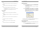
Default Mode
When Default Mode is selected and the Server Properties are Updated
(
Saved) all the configuration settings return to their default values. The
default settings for the ESP904 serial ports are:
Console Mode for Port 1;
RS-232 mode for Ports 2, 3 and 4.
N
N
o
o
t
t
e
e
:
:
Refer to Chapter 5 for details on Server Configuration settings
Console Mode
In Console Mode the ESP904 Configuration Menu can be accessed from a
computer by connecting its RS-232 serial port to the ESP904’s Port 1. Since
the computer is a DTE device, and the ESP904 serial ports are configured as
DTEs (with DB-9M connectors), a null modem crossover cable must be
used.
In
Console Mode the default serial port settings are: 9600 baud, 8 data bits,
No parity, and 1 stop bit. From Windows, HyperTerminal with VT100
terminal emulation can be used for
Console Mode configuration.
N
N
o
o
t
t
e
e
:
:
Refer to Chapter 9 for details on Console Mode
Upgrade Mode
Using a similar connection setup to that used in Console Mode, firmware for
the ESP904 can be updated by connecting the ESP904 to a computer via Port
1, using RS-232. (Upgrading also can be done by communicating with the
ESP904 over the network connection, using the ESP Manager software and a
virtual COM port mapped to the ESP904 Port 1.)
N
N
o
o
t
t
e
e
:
:
Refer to Chapter 8 for details on Upgrade Mode