


Manual Documentation Number: ESP904-0504 Table of Figures I
B&B Electronics Mfg Co Inc – 707 Dayton Rd - PO Box 1040 - Ottawa IL 61350 - Ph 815-433-5100 - Fax 815-433-5104 – www.bb-elec.com
B&B Electronics Ltd – Westlink Commercial Park – Oranmore, Galway, Ireland – Ph +353 91-792444 – Fax +353 91-792445 – www.bb-europe.com
T
T
a
a
b
b
l
l
e
e
o
o
f
f
F
F
i
i
g
g
u
u
r
r
e
e
s
s
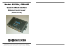
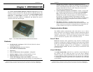
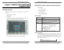
Figure 1. The VLINX ESP904 Quad-Port Ethernet Serial Server................................ 1
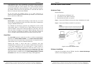
Figure 2. Quick Start Hardware Setup......................................................................... 4
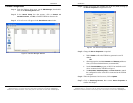
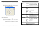
Figure 3. The ESP Manager Window........................................................................... 5
Figure 4. The Server Properties Window ..................................................................... 6
Figure 5. Configuring the Virtual COM Port............................................................... 7
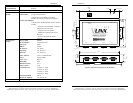
Figure 6. Dimensional Diagram of the ESP904......................................................... 10
Figure 7. Side View of the ESP904 – when vertically mounted.................................. 11
Figure 8. Top View of the ESP904.............................................................................. 13
Figure 9. The ESP904 Serial Port Connectors........................................................... 13
Figure 10. Internal Setting to Select RS-485 Bias ...................................................... 16
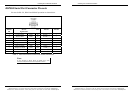
Table 11. Serial Connection Pin-outs for RS-232/RS-422/RS-485 ............................. 17
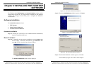
Figure 12. The Run Dialogue Box .............................................................................. 19
Figure 13. The Install Shield Wizard Window............................................................ 20
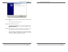
Figure 14. VLINX ESP Setup Window........................................................................ 20
Figure 15. The Choose Destination Window.............................................................. 20
Figure 16. The Install Shield Wizard Complete Window............................................ 21
Figure 17. Ethernet Connection via a LAN ................................................................ 23
Figure 18. Direct Ethernet Connection using a Crossover Cable.............................. 24
Figure 19. The VLINX ESP Manager Window........................................................... 25
Figure 20. The Search Setup Window......................................................................... 28
Figure 21. The Server Properties Window ................................................................. 29
Figure 22. The vcomui Window.................................................................................. 30
Figure 23. The Search Setup Window......................................................................... 37
Figure 24. The Found Server Window........................................................................ 38
Figure 25. The COMInst Window............................................................................... 38
Figure 26. The Windows Logo Testing Window......................................................... 39
Figure 27. The Device Manager Window................................................................... 40
Figure 28. The VLINX ESP (COM3) Properties Window........................................... 41
Figure 29. The ESP Manager Window....................................................................... 43
Figure 30. The vcomui Dialogue Box......................................................................... 44
Figure 31. The Control Panel Window....................................................................... 45
Figure 32. The Device Manager Window................................................................... 45
Figure 33. Confirm Device Removal .......................................................................... 46
Figure 34. The Port Settings Window......................................................................... 48
Figure 35. Upgrading in Progress.............................................................................. 49
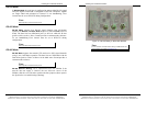
Figure 36. The Console Mode Server Configuration Screen...................................... 52
Figure 37. Saving and Restarting the Configuration.................................................. 53
Figure 38. Assigning a Password ............................................................................... 54
II Table of Figures Manual Documentation Number: ESP904-0504
B&B Electronics Mfg Co Inc – 707 Dayton Rd - PO Box 1040 - Ottawa IL 61350 - Ph 815-433-5100 - Fax 815-433-5104 – www.bb-elec.com
B&B Electronics Ltd – Westlink Commercial Park – Oranmore, Galway, Ireland – Ph +353 91-792444 – Fax +353 91-792445 – www.bb-europe.com
Figure 39. The Web Server Page................................................................................ 55
Figure 40. The Web Server Serial Port Properties Page............................................ 56
Figure 41. RS-232 Connections in a DB-9 Connector................................................ 57
Figure 42. Straight-through (DTE to DCE) DB-9 to DB-9 Serial Cable with RS-232
Signal Designations............................................................................................. 58
Figure 43. Crossover (DTE to DTE) DB-9 to DB-9 Serial Cable with RS-232 Signal
Designations........................................................................................................ 58
Figure 44. Connections for a DB-9 to DB-25 Straight-through Cable....................... 59
Figure 45. Connections for a DB-9 to DB-25 Crossover (null modem) Cable........... 59
Figure 46. Loopback Connections for RS-232............................................................ 60
Figure 47. RS-422 Connections in a DB-9 Connector................................................ 61
Figure 48. RS-422 Connections with Flow Control.................................................... 62
Figure 49. Loopback Connections for RS-422............................................................ 63
Figure 50. RS-422 Connection with No Flow Control................................................ 63
Figure 51. DB-9 Pin-out in RS-485 Mode .................................................................. 65
Figure 52. 2-wire RS-485 Connection........................................................................ 65
Figure 53. Pin-out for a Standard Ethernet Cable ..................................................... 67
Figure 54. Pin-out for a Crossover Ethernet Cable.................................................... 68