


INSTALLATION
17
Note: If the Switches do not enumerate correctly, reset the Master switch
(BANK 00) by simultaneously pressing the “BANK Up” and “BANK Down”
buttons. You can also reset the Master switch to detect newly added Slave
switches. If the switches still do not enumerate correctly, check that all
switches have the correct BANK address assigned to them and that all
daisy-chain cables are connected properly.
12. Verify that the Master unit has detected all Slave switches by
scrolling through the BANKs using the “BANK Up” and “BANK Down”
buttons. If all Slave switches are detected properly, the LED display
on the Master switch will register and display the attached Slave
switch’s BANK address.
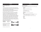
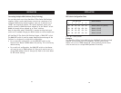
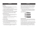
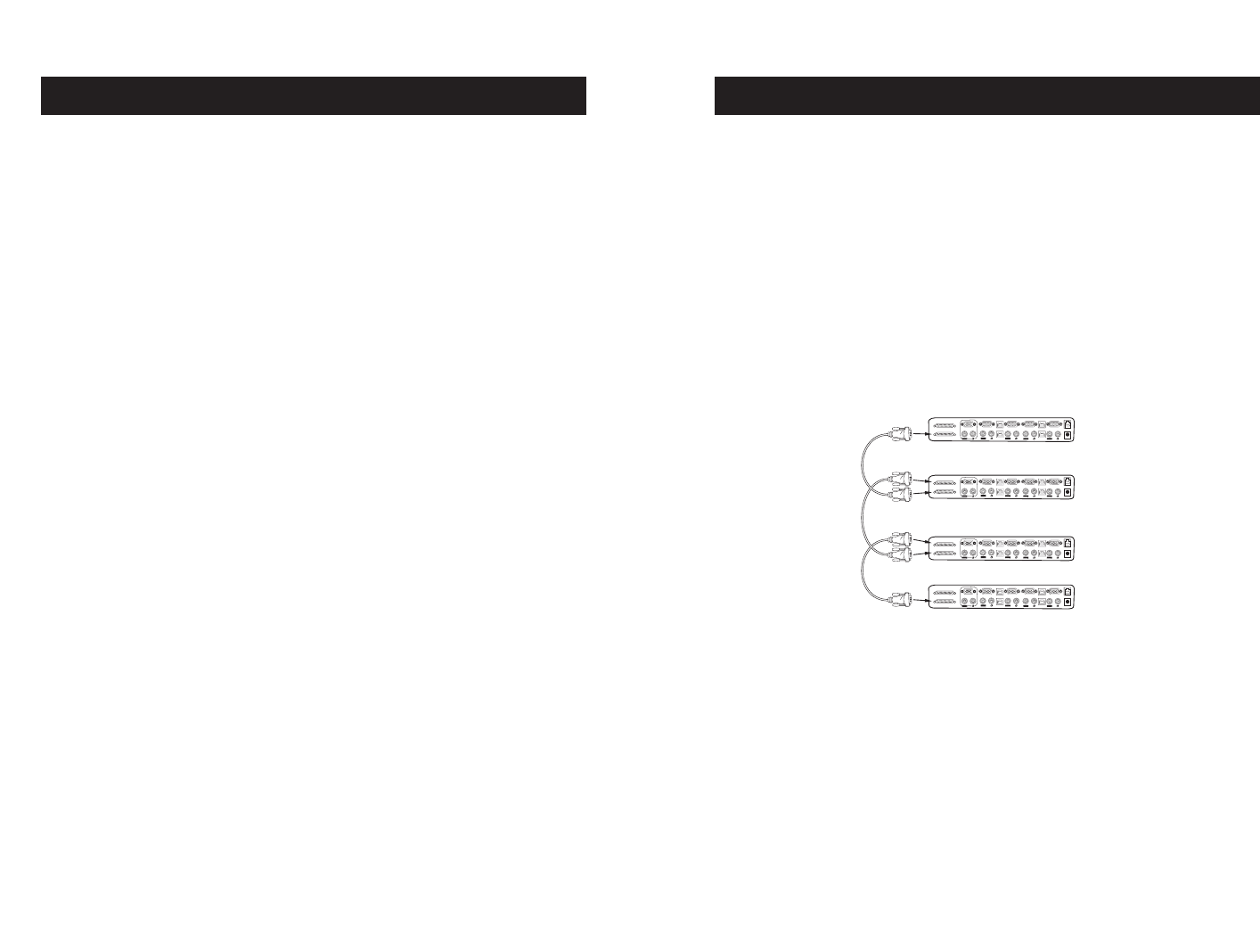
Example of Daisy-Chain Configuration
Powering Up the Systems
Once all cables have been connected, power up the computers that are
attached to the Switch. All computers can be powered on simultaneously.
The Switch emulates both a mouse and keyboard on each port and allows
your computer to boot normally.
The computer connected to port 1 will be displayed on the monitor. Check
to see that the keyboard, monitor, and mouse are working normally. Proceed
to do this with all occupied ports to verify that all computers are connected
and responding correctly. If you encounter an error, check your cable
connections for that computer and reboot. If the problem persists, please
refer to the Troubleshooting section of this manual. Now that you have
connected your console and computers to your Switch, it is ready for use.
INSTALLATION
16
Installation
Before you begin:
1. Make sure that all computers are powered off and that each Switch
has been assigned a unique BANK address.
2. Place Master and Slave switches in the desired location. Make sure all
are turned off and unplugged from the power source.
3. Connect the Console monitor, keyboard, and mouse to the Console ports of
the Master switch or BANK 00, as described previously in this User Manual.
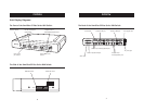
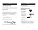
Connecting the Master Switch to First Slave Switch
4. Using the daisy-chain cable (F1D108-CBL), connect one end of the cable
to the “Master Input/Slave Output” port on the Master switch or “BANK 00”.
5. Connect the other end of the daisy-chain cable to the “Master
Input/Slave Output” port of the first Slave switch or “BANK 01”.
Adding Additional Slave Units
6. Using the daisy-chain cable (F1D108-CBL), connect one end of the
cable to the available daisy-chain port labeled “Slave Input” on the
Slave switch (for example, BANK 01).
7. Connect the other end of the daisy-chain cable to the “Master
Input/Slave Output” port of the Slave switch that you are adding (for
example, BANK 02).
8. Repeat steps 5 and 6 for additional switches you wish to
daisy-chain together.
Connecting the Computers
9. Connect all computers to the Master and Slave switches. Refer to the
section in this manual titled “Single KVM Switch Installation” for instruction
on how to connect the Console and the computers to the Switch.
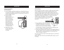
10. Connect the power supply to the Master switch first and power up the
Switch. You should see the Switch light up and display the digits
“00”, indicating its BANK address.
11. Power up the Slave switches sequentially, beginning with BANK 01,
by connecting each unit’s power supply. Each switch should display
its corresponding BANK address number as it is powered up.
VGA
VGA
VGA
VGA
VGA
USB
USB
USB
USB
04
04
04
03
03
03
02
02
02
01
01
01
Slave Input
Master Input/Slave Output
VGA
VGA
VGA
VGA
VGA
USB
USB
USB
USB
04
04
04
03
03
03
02
02
02
01
01
01
Slave Input
Master Input/Slave Output
VGA
VGA
VGA
VGA
VGA
USB
USB
USB
USB
04
04
04
03
03
03
02
02
02
01
01
01
Slave Input
Master Input/Slave Output
VGA
VGA
VGA
VGA
VGA
USB
USB
USB
USB
04
04
04
03
03
03
02
02
02
01
01
01
Slave Input
Master Input/Slave Output
cable 1
cable 2
cable 3
Master unit (BANK 00)
Slave unit (BANK01)
Slave unit (BANK02)
Slave unit (BANK03)