


INSTALLATION
15
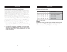
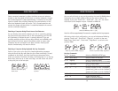
DIP Switch Configuration Chart
DIP SWITCH# BANK ADDRESS
123 456
ON ON ON ON ON ON BANK 00 MASTER (default)
ON ON OFF ON ON ON BANK 01 SLAVE
ON ON ON OFF ON ON BANK 02 SLAVE
ON ON OFF OFF ON ON BANK 03 SLAVE
Note: “On” is down position.
Example:
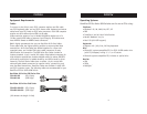
Four OmniView SE Plus Series KVM Switches (F1DZ104T) are daisy-chained
together for controlling up to 16 computers. The DIP switch on the
Master unit is set to “BANK address 00” (factory default) and the Slave
units are each set to a unique BANK (between 01 and 03).
INSTALLATION
14
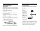
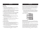
Connecting Multiple KVM Switches (Daisy-Chaining)
You can daisy-chain up to four OmniView SE Plus Series KVM Switches
together, giving a server administrator control over a maximum of 16
computers. When daisy-chained together, each unit is referred to as a
“BANK” and assigned an address. The Console keyboard, mouse, and
monitor connect to BANK 00 and are referred to as the “Master” switch.
BANKs 01 through 03 are referred to as “Slave” switches.
Note: A daisy-chain cable (F1D108-CBL) is required to daisy-chain each
switch and is available through your Belkin reseller or online at belkin.com.
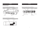
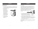
All OmniView SE Plus Series KVM Switches feature a “BANK DIP” switch.
The BANK DIP switch is used for proper identification and usage of the
Switches in a single-unit or daisy-chain configuration.
• For a single-unit configuration, set the BANK DIP switch on the
Switch to the “Master” (BANK address 00) setting. This is the factory
default setting.
• For a multi-unit configuration, the BANK DIP switch on the Master
unit must be set to “BANK address 00”. Slave units must be set to a
unique BANK address (from 01 through 03). Refer to the chart below
for DIP switch settings.