


INSTALLATION
11
Single KVM Switch Installation
This section provides complete instructions for the hardware setup of
a single SE Plus Series KVM Switch.
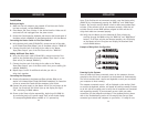
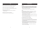
PS/2 Installation:
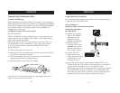
Keyboard, Video, and Mouse Connections
Connect the Console to
the KVM Switch
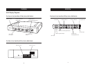
1. Connect your monitor
cable to the HDDB15
female port on the
back of the Switch
labeled "Console VGA”.
2. Connect the PS/2
keyboard cable to the
keyboard port on the
back of the Switch in
the “Console” section.
3. Connect the PS/2
mouse cable to the
mouse port on the back
of the Switch in the
“Console” section.
4. Attach the power supply to the connector labeled “DC 12V, 1A”
located on the rear of the Switch. Once the power is connected to
a power source, the LED for port 01 will begin flashing.
Sequentially push the direct-access buttons for ports 01 through 04
(02 for F1DZ102T and 04 for F1DZ104T). The corresponding LED
should flash as each button is pressed, indicating that the port is
ready for connecting your servers (computer connection).
1
2
3
4
5
6
7
8
9
+
-
=
/
0
num
lock
cap
lock
pg up
return
shift clt
alt
delete
P
[
]
'"
;:
L
K
=
-
09
8
PG UP
PG DN
HOME
HELP
CAPS
`
ESC
<
>
^
+
OPT
PC
F9
F10
F11
76543
2
1
INSTALLATION
10
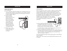
Step-by-Step Installation Guide
Cautions and Warnings
Before attempting to connect anything to the Switch or your computers,
please ensure that all equipment is powered off. Plugging and unplugging
cables while computers are powered on may cause irreversible damage to
the computers and/or the Switch(es). Belkin is not responsible for
damage caused in this way.
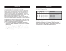
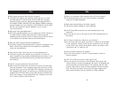
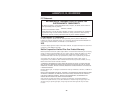
Installing the Switch into a Server Rack
Bracket Installation
The 4-Port KVM Switch can be installed into a server pack using the
optional mounting kit (F1D005). Please follow these simple steps to
achieve the desired adjustment.
Note: If this KVM Switch will be daisy-chained to another switch, set
the BANK address prior to installing on a rack. Refer to the section
in this User Manual labeled “Connecting Multiple KVM Switches
(Daisy-Chaining)”.
1. Attach the bracket to your Switch.
2. Determine how far you would like the Switch to protrude from the
rack. Select a bracket-hole scheme.
3. Attach the bracket to the side of your Switch with the Phillips
screws provided. (Refer to diagram below.)
4. Mount the Switch to the rack rail assembly.
Your Switch is now mounted securely into the bracket and you are
ready to connect cables to the back.