


2
30
Hardware Installation
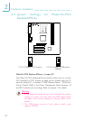
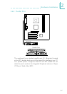
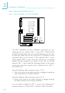
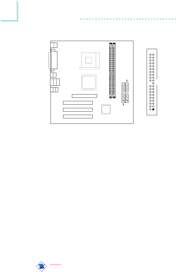
2.6.5 IDE Disk Drive Connector
The mainboard is equipped with two shrouded PCI IDE headers
that will interface four Enhanced IDE (Integrated Drive Electronics)
disk drives. To prevent improper IDE cable installation, each shrouded
PCI IDE header has a keying mechanism. The 40-pin connector on
the IDE cable can be placed into the header only if pin 1 of the
connector is aligned with pin 1 of the header. You can enable or
disable the onboard primary or secondary IDE controller in the
Integrated Peripherals submenu (VIA OnChip IDE Device field) of
the BIOS.
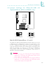
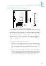
Connecting the IDE Disk Drive Cable
1. If you are connecting two IDE drives, install the 40-pin connector
of the IDE cable into the primary shrouded IDE header (J19). If
you are adding a third or fourth IDE device, install the 40-pin
connector of the other IDE cable into the secondary shrouded
IDE header (J23).
2. Install the other 40-pin header connector(s) into the device with
the colored edge of the ribbon cable aligned with pin 1 of the
drive edge connector(s).
Note:
Refer to your disk drive users manual for information about
selecting proper drive switch settings.
IDE 2
(J23)
IDE 1
(J19)
1
2
40
39