


14
SERVSWITCH™ USB AND USB PLUS
2.3 The ServSwitch USB Illustrated
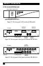
Figure 2-1. The front panel of all ServSwitch USB models.
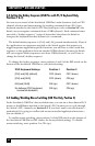
Figure 2-2. The rear panel of the 2-port ServSwitch USB (KV812A).
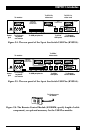
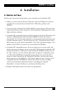
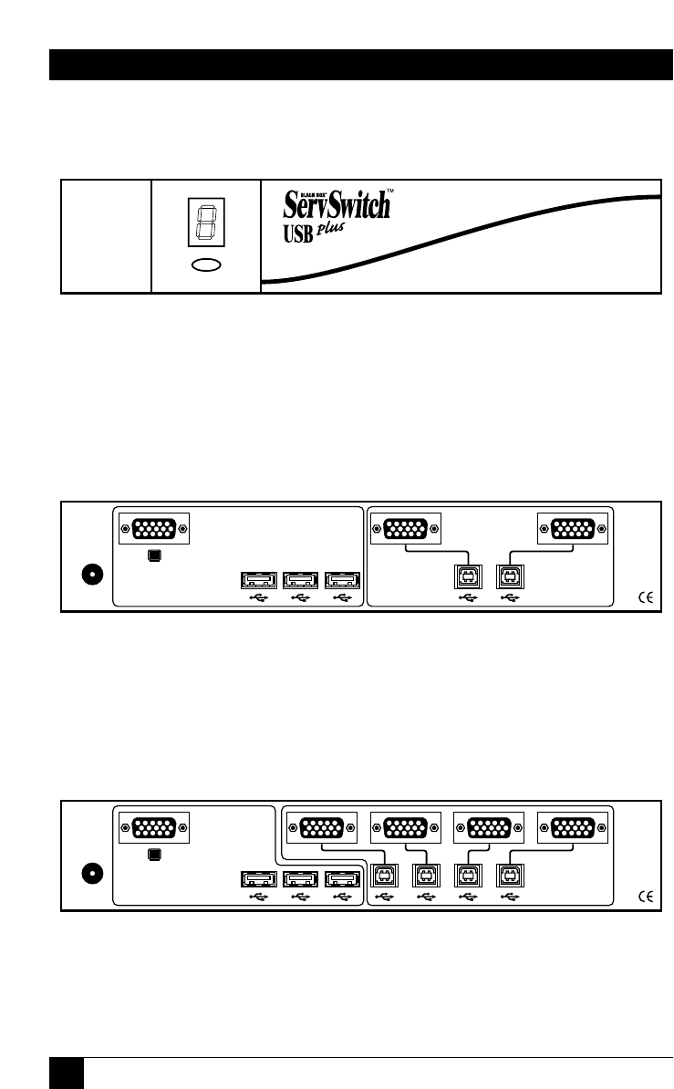
Figure 2-3. The rear panel of the 4-port ServSwitch USB (KV814A).
5V DC, 2A
KV814A
USER AND
PERIPHERAL
CONNECTIONS
43 21
CPU
CONNECTIONS
5V DC, 2A
KV812A
1
CPU
CONNECTIONS
2
USER AND
PERIPHERAL
CONNECTIONS
Channel-selection button
(also used to trigger firmware-version
display and autoscanning; see Section 5.2)
Status display (7-segment LED)
To monitor
To CPU 2’s
video card
To CPU 1’s
video card
To CPU 2’s
USB port
To CPU 1’s
USB port
Power jack
To USB peripherals
To monitor
To CPUs’
video cards
To CPUs’
USB ports
Power jack
To USB peripherals