


20
LINESHARE PRO
NOTE
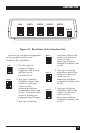
The RJ-11 jacks have four (4)
posts: The red post is
marked [R], the green post is
marked [G], the yellow post
is marked [Y], and the black
post is marked [B].
2. Locate the telephone line from
the phone company after it
enters the premises but before it
routes to any phone jack.
3. With the utility knife, cut into
the cable to expose the red,
green, yellow, and black wires.
NOTE
If the color codes of the
wires are not red, green,
yellow, and black, call
technical support for further
instructions.
4. Cut the red and green wires and
expose the copper wire, while
leaving the yellow and black
wires intact.
No phone in the location should
have dial tone on this line.
5. Connect the cut wires from the
phone company to jack
“Number 1” by attaching the red
wire to the red post and the
green wire to the green post.
6. Connect the cut wires that feed
all the phones in the location to
jack “Number 2” by attaching
the red wire to the red post and
the green wire to the green post.
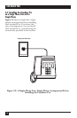
7. Plug one end of a phone cable
into jack “Number 1.”
8. Plug the other end of the phone
cable into the LINE port on the
rear panel of the Lineshare Pro.
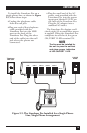
9. Plug one end of the second
phone cable into PORT 1 on the
rear panel of the Lineshare Pro.
10. Plug the other end of the
phone cable into jack “Number
2.”
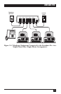
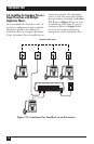
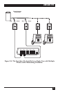
11. Connect the other telephone
equipment as shown in Figure
3-4.
If the Lineshare Pro is not located
near the other equipment, you may
need to run additional telephone
wiring to the equipment to complete
this installation.