


14
RS-422/485 SERIAL INTERFACE PLUS, 4-PORT
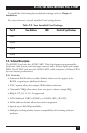
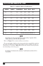
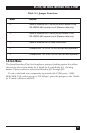
Table 3-3. Port to Connector Table.
Port # Connector Location Address Example (Base=2E0)
1 1 Base+0 2E0-2E7
2 2 Base+8 2E8-2EF
3 3 Base+16 2F0-2F7
4 4 Base+24 2F8-2FF
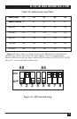
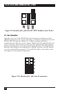
3.2 Jumper Selections
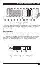
For ease of configuration, the headers are grouped by port. Port 1 headers
have a
“
J1” prefix, Port 2 headers have the “J2” prefix, etc. For example, the
header that controls the Port 1 IRQ selection is J1B, the header that controls
the Port 2 IRQ selection is J2B. Information for configuring the adapter is
printed directly on the Card. This is particularly useful in field re-
configuration.
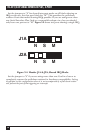
3.3 IRQ Selection
Headers J1B through J4B select the interrupt request for each serial port. If
COM1: is selected, the corresponding jumper must be on the IRQ4 setting. If
COM2: is selected, the corresponding jumper must be on IRQ3.
NOTE
Most communications software applications default COM3: to IRQ4 and COM4:
to IRQ3. This requires the sharing of interrupts between COM1: and COM3:,
and between COM2: and COM4:. While this is the default, it is not always the
best setting. Check your software configuration instructions to determine the
most appropriate IRQ selection.