


10
RS-422/485 SERIAL INTERFACE PLUS, 4-PORT
2.4.2 M
ODEM
C
ONTROL
S
IGNALS
Some software packages require the use of modem handshake signals such as
CTS or DCD. Refer to your application software manual to determine the
requirements for modem control signals. If no requirements are mentioned,
a safe configuration is to tie DTR to DSR and DCD, and tie RTS to CTS. This
configuration will typically satisfy the modem control-signal requirements for
most communications software.
2.4.3 I
NTERRUPTS
A good analogy of a PC interrupt would be a phone ringing. The phone “bell”
is a request for us to stop what we are currently doing and take up another
task (speak to the person on the other end of the line). This is the same
process the PC uses to alert the CPU that a task must be performed. The CPU,
upon receiving an interrupt, makes a record of what the processor was doing
at the time and stores the information in the “stack”; this allows the processor
to resume its predefined duties after the interrupt is handled, exactly where it
left off. Every main subsystem in the PC has its own interrupt, frequently
called an IRQ (short for Interrupt ReQuest).
2.4.4 W
HY
U
SE AN
ISP?
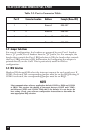
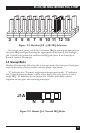
An Interrupt Status Port (ISP) is a read-only, 8-bit register that sets a
corresponding bit when an interrupt is pending. Port 1 interrupt line
corresponds with Bit D0 of the status port, Port 2 with D1, etc. The use of this
port means that the software designer now only has to poll a single port to
determine if an interrupt is pending.
The ISP is at Base+7 on each port (Example: Base=280 Hex, Status
Port=287, 28F...etc.). The RS-422/485 Serial Interface Plus Card will allow any
one of the available locations to be read to obtain the value in the status port.
All four status ports on the Card are identical, so any one of the four can be
read.
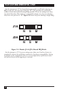
Example: This indicates that Port 2 has an interrupt pending.
Bit Position: 76543210
Value Read: 0000001 0