


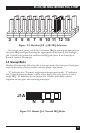

15
RS-422/485 SERIAL INTERFACE PLUS, 4-PORT
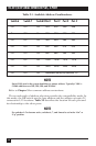
3 4 5 6 7 9 10 11 12 15
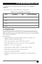
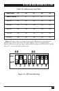
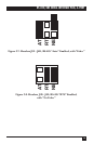
Figure 3-2. Headers J1B – J4B, IRQ Selection.
Any two or more ports can share a common IRQ by placing the jumpers on
the same IRQ setting and setting the appropriate selections at J1A through
J4A. Consult your particular software for IRQ selection. If no interrupt is
desired, remove the jumper.
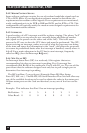
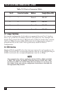
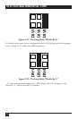
3.4 Interrupt Modes
Headers J1A through J4A select the interrupt modes for each port. Each port
must be set in the correct mode to ensure proper operation.
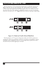
“N” indicates the (N)ormal, single-interrupt-per-port mode. “S” indicates
the (S)hared interrupt mode, which allows more than one port to access a
single IRQ. ‘M’ indicates the inclusion of a 1-Kohm pull-down resistor
required on one port when sharing interrupts.
N S M
J1A
Figure 3-3. Header J1A, Normal IRQ Mode.