


31
RS-422/485 SERIAL INTERFACE PLUS, 4-PORT
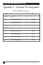
Appendix C: Electrical Interface
RS-422
The RS-422 specification defines the electrical characteristics of balanced-
voltage digital interface circuits. RS-422 is a differential interface that defines
voltage levels and driver/receiver electrical specifications. On a differential
interface, logic levels are defined by the difference in voltage between a pair
of outputs or inputs. In contrast, a single-ended interface, for example RS-
232, defines the logic levels as the difference in voltage between a single
signal and a common ground connection. Differential interfaces are typically
more immune to noise or voltage spikes that may occur on the
communication lines. Differential interfaces also have greater drive
capabilities that allow for longer cable lengths. RS-422 is rated up to 10
Megabits per second and can have cabling 4000 feet (1219 m) long.
RS-422 also defines driver and receiver electrical characteristics that will allow
1 driver and up to 32 receivers on the line at once. RS-422 signal levels range
from 0 to +5 volts. RS-422 does not define a physical connector.
RS-485
RS-485 is backward-compatible with RS-422; however, it is optimized for
partyline or multi-drop applications. The output of the RS-422/485 driver is
capable of being Active (enabled) or Tri-State (disabled). This capability
allows multiple ports to be connected in a multi-drop bus and selectively
polled. RS-485 allows cable lengths up to 4000 feet (1219 m) and data rates
up to 10 Megabits per second. The signal levels for RS-485 are the same as
those defined by RS-422. RS-485 has electrical characteristics that allow for 32
drivers and 32 receivers to be connected to one line. This interface is ideal for
multi-drop or network environments. RS-485’s tri-state driver (not dual-state)
will allow the electrical presence of the driver to be removed from the line.
Only one driver may be active at a time and the other driver(s) must be tri-
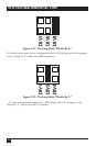
stated. RS-485 can be cabled in two ways, two-wire and four-wire mode. Two-
wire mode does not allow for full-duplex communication, and requires that
data be transferred in only one direction at a time. For half-duplex operation,
the two transmit pins should be connected to the two receive pins (Tx+ to
Rx+ and Tx- to Rx-). Four-wire mode allows full-duplex data transfers. RS-485
does not define a connector pin-out or a set of modem control signals. RS-485
does not define a physical connector.