


17
RS-422/485 SERIAL INTERFACE PLUS, 4-PORT
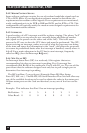
3.5 RS-485 Enable Modes
RS-485 is ideal for multi-drop or network environments. RS-485 requires a tri-
state driver (not dual-state) that will allow the electrical presence of the driver
to be removed from the line. The driver is in a tri-state or high-impedance
condition when this occurs. Only one driver may be active at a time and the
other driver(s) must be tri-stated. The output modem control signal Request
To Send (RTS) is typically used to control the state of the driver. Some
communication software packages refer to RS-485 as RTS enable or RTS
block-mode transfer.
One of the unique features of the Serial Interface Plus Card is the ability to
be RS-485 compatible without the need for special software or drivers. This
ability is especially useful in Windows, Windows NT, and OS/2 environments
where the lower-level I/O control is abstracted from the application program.
This ability means that you can effectively use the Card in an RS-485
application with existing standard RS-232 software drivers.
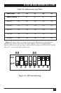
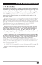
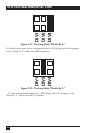
Headers J1D through J4D are used to control the RS-485 mode functions
for the driver circuit. The selections are
“
RTS” enable (silk-screen “RT”) or
“Auto” enable (silk-screen “AE”). The “Auto” enable feature automatically
enables/disables the RS-485 interface. The “RTS” mode uses the “RTS”
modem control signal to enable the RS-485 interface and provides backward
compatibility with existing software products.
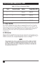
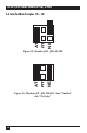
Position 3 (silk-screen “NE”) of J1D through J4D is used to control the RS-
485 enable/disable functions for the receiver circuit and determine the state
of the RS-422/485 driver. The RS-485 “Echo” is the result of connecting the
receiver inputs to the transmitter outputs. Every time a character is
transmitted, it is also received. This can be beneficial if the software can
handle echoing using received characters to throttle the transmitter or it can
confuse the system if the software does not. To select the “No Echo” mode
select silk-screen position “NE.”
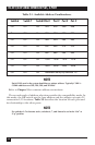
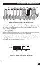
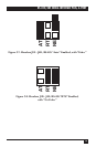
For RS-422/530/449 compatibility, remove the jumpers at J1D through J4D.
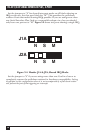
Examples on the following pages describe all of the valid settings for
J1D-J4D.