


11
CHAPTER 4: Technical Description
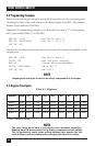
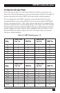
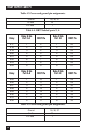
4.6 Connector and Jumper Pinout
Each relay has two sides, an A side and a B side. Each side is connected to two
places: the cable and the jumpers on the top of the board. Tables 4-2 through 4-5
provide the pinouts for the two DB37 cable ends and the onboard jumpers.
For easy wiring, the card’s DB37 connector can be interfaced directly to the
terminal block kit (if you ordered IC907C, you’ll need part number EDN37-SP).
The kit, consisting of a 6-ft. (1.8-m) male/female cable and screw terminal block,
provides a simple means to connect field wiring to the 37-pin cards. The terminal
block provides both male and female DB37 connectors, eliminating the need for
gender changers and other adapters while simplifying cable connections. If you
ordered IC908C (the Relay Output Card PCI—32 Outputs/Kit), the terminal
blocks are already included.
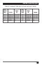
Table 4-2. DB37 labeled ports 1, 2.
Relay A Side Relay B Side
Relay Port 1-A DB37 Pin Port 1-B DB37 Pin
K1 1 2 1 20
K2 2 3 2 21
K3 3 4 3 22
K4 4 5 4 23
K5 5 6 5 24
K6 6 7 6 25
K7 7 8 7 26
K8 8 9 8 27
Relay A Side Relay B Side
Relay Port 2-A DB37 Pin Port 2-B DB37 Pin
K9 1 10 1 28
K10 2 11 2 29
K11 3 12 3 30
K12 4 13 4 31
K13 5 14 5 32
K14 6 15 6 33
K15 7 16 7 34
K16 8 17 8 35