


13
CHAPTER 4: Technical Description
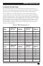
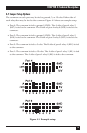
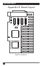
4.7 Jumper Setup Options
The common on each port may be tied to ground, 5, or 12 volts. Either side of
each relay then may be tied to the common. Figure 4-1 shows an example setup.
• Port 4: The common is tied to ground (GND). The A side of port-4 relay 3
(K27) is tied to the common. The B side of port-4 relay 6 (K30) is tied to the
common.
• Port 3: The common is tied to ground (GND). The A side of port-3 relay 2
(K18) is tied to the common. The B side of port-3 relay 5 (K21) is tied to the
common.
• Port 2: The common is tied to 5 volts. The B side of port-2 relay 4 (K12) is tied
to the common.
• Port 1: The common is tied to 12 volts. The A side of port-1 relay 1 (K1) is tied
to the common. The A side of port-1 relay 8 (K8) is tied to the common.
Figure 4-1. Example setup.