


Black Box Networks PICO systems
Pico Manual v5.1
V5.1 18
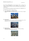
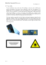
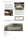
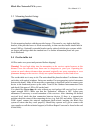
5. Fine Adjustment is required after the
unit has been aligned with the
internal pointing device. Fine
alignment is applicable for vertical
and horizontal orientations. These
movements must be done using the
fine alignment screws Adjust first
the horizontal then the vertical screw
as shown in the photographs on this page.
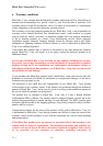
Adjust these screws while watching the
rear panel LED lights(see diagram:3.2).
Illuminate as many green LED power
indication lights as possible during the
fine alignment process, and follow your
multimeter display, to find the maximum
of the detector voltage.
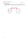
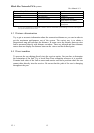
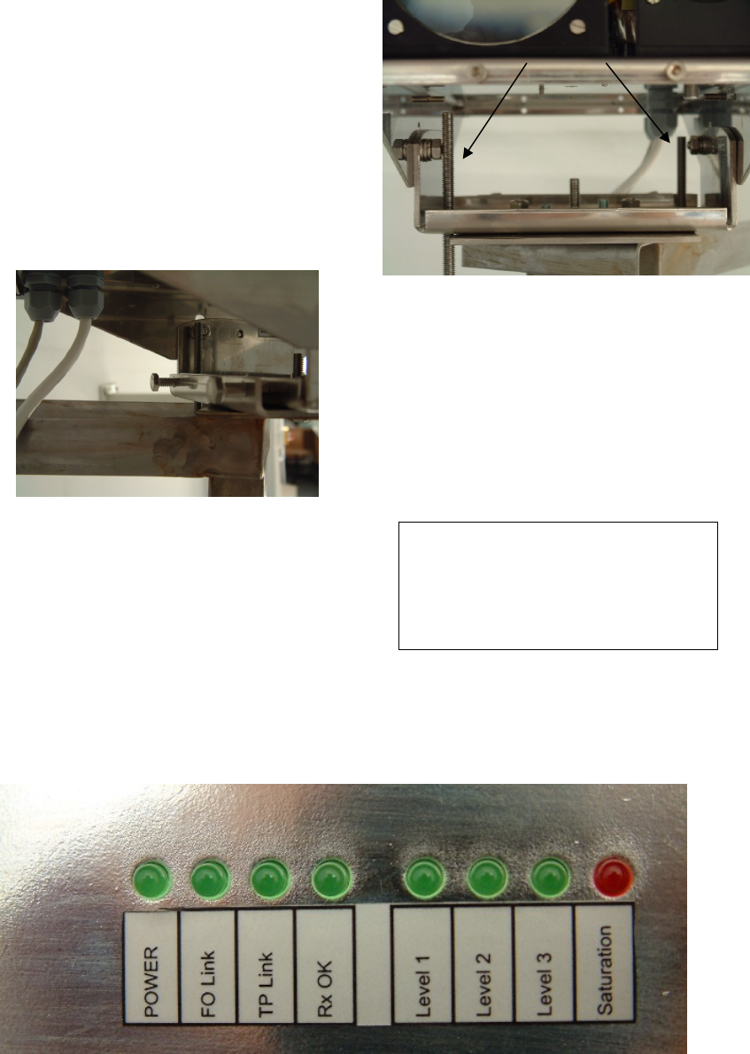
6. During this period described in the fifth step, try to avoid the saturation LED. /Red
light/ (See Diagram 5.2)
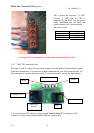
Diagram 5.2
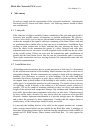
LED Meanings:
Power:
The head is powered up.
FO Link:
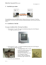
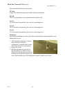
Horizontal Fine
Alignment screws
DON’T TRY TO DO MOVE
TWO HEADS AT THE SAME
TIME! The result won’t be the
same