


AutoDome Power Supply Boxes Installing the Power Supply Box | en 21
Bosch Security Systems, Inc. Installation Guide F.01U.250.895 | 1.0 | 2011.08
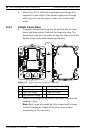
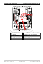
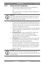
2.4.2 Wiring the Power Supply Box
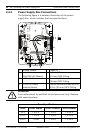
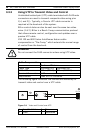
1. Route the high voltage 115/230 VAC lines through the
conduit fitting on the left side of the box.
or
Route the 24 VAC lines through the conduit fitting on the
left side of the box.
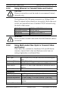
2. Cut and trim the high voltage 24/115/230 VAC power and
ground wires with sufficient slack to reach their connector
terminal in the box, but not so long as to be pinched by or
to obstruct closing the cover door.
3. Attach the supplied 3-pin power plug to the incoming high
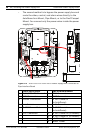
voltage power wires in the box. Refer to connector P101 in
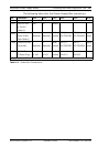
Table 2.1, Page 23.
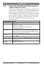
4. Analog AutoDome: If you are using UTP for video, route
the UTP cable out to where the AutoDome will be
mounted. Refer to Section 3 Cable and Wire Standards,
page 24 for fiber optic specifications.
5. IP AutoDome: Route the Ethernet cable out to where the
AutoDome will be mounted. Refer to Section 3 Cable and
Wire Standards, page 24 for specifications.
6. Route the low power 24 VAC wires from the right side of
the power supply box out to where the AutoDome will be
mounted. Attach the supplied 5-pin 24 VAC Dome plug to
the wire ends inside the box. Refer to connector P107 in
Table 2.1, Page 23.
NOTICE!
The power supply box with transformer comes with a barrier
that separates the high voltage side on the left from the low
voltage 24 VAC side on the right.
NOTICE!
All video, control, and alarm wires either pass through the
power supply box or by-pass it and connect directly to the Pipe
Interface Board.